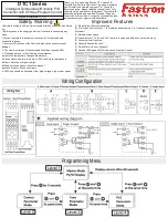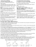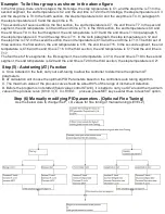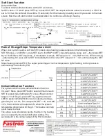
1. Sensor Type Setting
A. Press SET +◄ key to enter LEVEL3
B. Once you reach INP Press ◄ and the SV
display will blink
C. Press▼or▲select the input type (refer to the
signal input selection table). Press SET to confirm
E. At the same time, press SET +◄ to return to
LEVEL1
2. AL1/AL2 Alarm mode setting
A. Press SET for 5 seconds to enter LEVEL2
B. Press SET several times to access AD1, then press the
◄ key and the display will start to flash.
C. Press▼or▲select the alarm type (see alarm selection
table)
D. Press SET to confirm
E. Press SET to return to LEVEL 1
Step (3): Set alarm value AL1/AL2
See AL1 and AL2 in alarm mode Table
A. Press SET key several times to access AL1
selection, and then press ◄ to enable the
selection.
B. Press▲ or▼ to SET the value, and then press
the ◄ key to move to the next digit and do Both
AL1 and AL2 can choose alarm mode from 0 to 10,
which can the same setting .
C. After setting, press SET key to confirm. Pattern
End output can be selected as Alarm mode 11.
There is also a constant temperature and timing
alarm mode 19
D. Press SET to return to LEVEL1 setting and test
the alarm function or pattern end output.
Step (4): Program Control Setting and
Operation (Optional)
A. At LEVEL1 master PV/SV display press SET key several
times to reach “C01” in order to start to set the program.
Press ◄ and ▲ or▼ and SET to set the temperature for the
frist segment.
B. Press SET to select T01. Press ◄ and ▲ or▼ and SET
to set the time for the frist segment.
C. Press SET several times until you reach OU01. Press ◄
and ▲ or▼ and SET to set the MV high limit for the first
segment. Repeat for each step to create the pattern.
D. Ensure all remaining CX, TX and OUX values are set to
0
You may want to setup multiple patterns.
E. Note that when presetting of segments Is complete, CX, TX and OUX of the next segment must all be put"0"
as the isolation segment and mark between groups.
E. 60 is the maximum of segments.
G.CAL setting is the first step number of the startup operation group. For example, if the second groups begins
at C08, then CAL should be set to 08.
F. If the program Control needs to start from 0 Deg C, set STA parameter to 1; if PV is needed, put the STA item
into 2 or 3. Program control END mode has two options see operation flow chart (end of LEVEL 3)
G. During operation the program segment or step number you can change the current segment/step number to
run forward or backward within the range of the current group; Select St item to see the current step time of the
current running segment in order to know where exactly in the program you are curretly operating.
H. To start/end the program, please press SET key and ▲ key at the same time.
I. Press the ▲ button to pause/continue the program.
J. To ensure the controller reaches the desired temperature regardless of the time period, you can select Wait
Value (WB) in the range of (0.110 Deg C), WB=0 means the controller will advance even if the set
temperature is not reached. See end lf LEVEL 3 menu
K. The controller will start either by shorting terminals 6 and 7, or by pressing the
·Press the ▲ and SET key once (34 seconds) to start the program control; if press the ▲ and SET key once
again (34 seconds) program control will end; · during the program control operation, press ▲ key once (12
seconds) to pause the program control. If press the ▲key again program control will continue to run.
Summary of Contents for DTC1 Series
Page 2: ......


