2007-11-19
Page 11 of 35
IT321_Tech_doc_12
3. OPERATION
3.1 Operating modes
After power up the IT321 module (with Flash version) boots from the
internal ROM or from flash memory depending on the BOOT1 and
BOOT2 control inputs (see Table 4).
With ROM code version the BOOT1 & 2 inputs can be left uncon-
nected but the inputs GPIO6 & 2 determine baud rate and protocol
selection (see Table 3). Modes of operation:
•
Normal mode (Navigation)
o
Power management system modes
•
Hibernate mode
•
Programming mode
3.2 Normal mode
The IT321 receiver will start navigation automatically after power up
using all (if any) aiding information on GPS time, satellite ephemeris
and Last Known Good (LKG) position information provided by the
non-volatile back up block (RTC & RAM). The power consumption will
vary depending on the amount of satellite acquisitions and number of
satellites in track. This mode is also referenced as
Full Power
or
Navigation
state.
Navigation is available and any configuration settings are valid as
long as the VDD power supply is active. When the VDD is powered
off, settings are reset to factory configuration and receiver performs a
cold start on next power up.
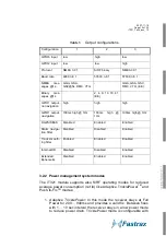
3.2.1 Output configuration
With ROM code version user can select the data output configuration
by setting the GPIO 6 and 2, which are read at power up. Configura-
tion is selected by setting GPIO 6 and 13 to low or high state accord-
ing to the following table.
Summary of Contents for IT321
Page 15: ...2007 11 19 Page 15 of 35 IT321_Tech_doc_12 Figure 2 SiRFFlash utility settings...
Page 25: ...2007 11 19 Page 25 of 35 IT321_Tech_doc_12 Figure 7 Tape and reel specification...
Page 32: ...2007 11 19 Page 32 of 35 IT321_Tech_doc_12 7 3 Circuit drawing rev C...
Page 34: ...2007 11 19 Page 34 of 35 IT321_Tech_doc_12 7 6 Artwork layer 2 rev C 7 7 Artwork layer 3 rev C...
Page 35: ...2007 11 19 Page 35 of 35 IT321_Tech_doc_12 7 8 Artwork layer 4 Bottom rev C...


