REBUILD INSTRUCTIONS
www.fastestinc.com
Roseville, MN
Toll Free at 1-800-444-2373
Fax 651-645-7390
PAT# 6,039,303
WP085 Rev B 04/2009
(1)ADD
SPRING
(2)ADD
BODY
SLIDE
SLEEVE
STEP
COMPLETE
LEAVE ROOM
FOR LATCH
PINS
ASSEMBLE IN
ORDER SHOWN
TAPERED
END
TORQUE TO
10FT-LBS
SLIDE
SLEEVE
INSERT
PINS
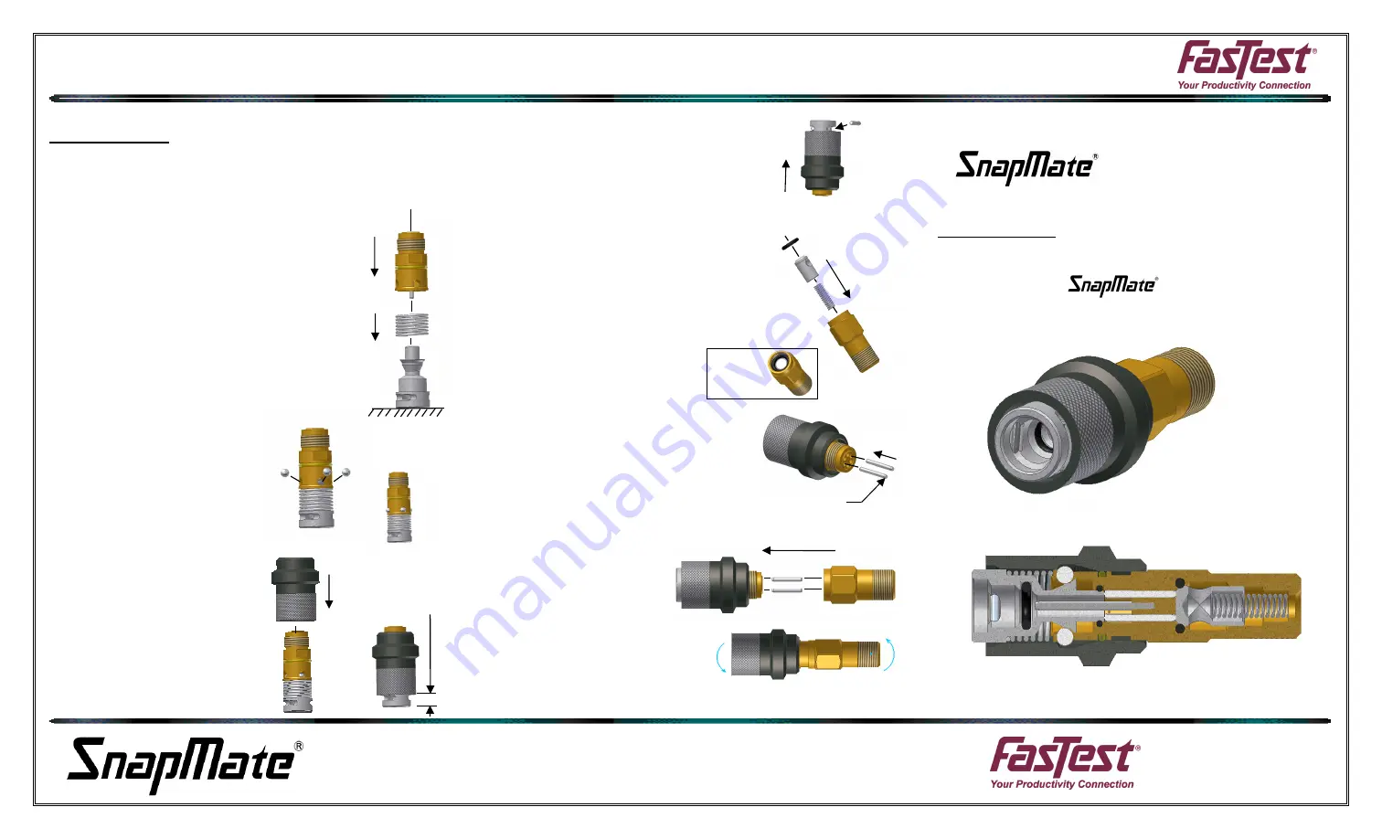
REASSEMBLE:
Use all the new seals provided and lubricate lightly with an oil
compatible with your system / process during assembly. Re-
place pins with new pins as provided in the rebuild kit.
1) Place piston with end facing down on
solid surface and add the piston spring.
2) With the piston seal and sleeve o-ring
already replaced, slide the front body
over the back of the piston. This will re-
quire some force but if properly lubricat-
ed, it will slide over without damaging
the seal.
3) Continue to compress the
front body over the piston and
add the 4 balls into their re-
spective holes. Do not re-
lease the pressure until step 4
is complete.
4) Slide the sleeve over the
compressed assembly up to
the grip pin slots.
5) Flip the connector over and inset the
latch pins. Slide the sleeve over the
pins to retain.
6) Insert the spring and poppet into the
back body.
7) Lightly lubricate the poppet seal and in-
sert into the back body above the pop-
pet.
8) Insert the poppet pins into the back of
the front body. Make sure the poppet
pins have the tapered side toward the
poppet. Pins are not required to be
placed in any specific holes but they
must be placed opposing.
9) Use a drop of LocTite
242
on
the
body
threads and assemble
the two body halves.
Tighten threads to 10ft-
lbs.
SCPR50 Rebuild Kit
Valved In-Line
DESCRIPTION:
Rebuild kit for internally valved,
in-line with pin grip.
INSERT
PINS
STEP 6&7
SUB-ASSEMBLY