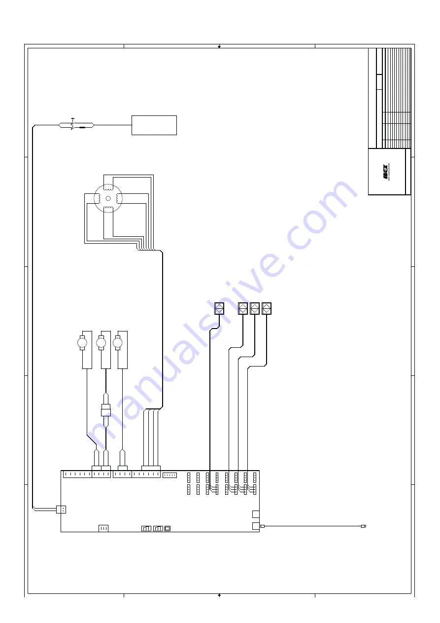
background image

Electrical scheme

5

5

4

4

3

3

2

2

1

1

D

D

C

C

B

B

A

A

+-

-

-

+

+

SENSO

R

 1

 1861975

M

O

T

O

R

 1

 (

1

8

61988)

N

E

W

 1

814540

SENSOR 4 (1

861978)

NEW: 181

4

5

6

3

SENSOR 6 (1

861980)

NEW: 181

4

5

6

7

SENSOR 2 (1

861976)

NEW: 181

4

5

6

8

CABLE

 3

1

 1862742

BLUE

BLACK

BROWN

BLUE

BLACK

BROWN

1

2

4

6

12722

3

0

TO RS232 PC

P

O

W

E

R

SUPPLY 24VDC

POWERSUP

P

LY

 ASSY 1862749

S

U

PPLY 110/230VAC

50-60Hz, 1Am

ax

M

O

TOR ASSY

18145

4

2

M

O

TOR ASSY

11300

7

1

M

O

TOR ASSY

18145

4

1

CABLE

 3

3

 1862744

Friday, November 

28, 

2008

11

TM300

V1.1

0.1

10-3-2008

Nv

B


First

 version

Added agit & t

tmotorcable

Remov

ed agitmotor ex

t. 

cable

Changed name to 1.1, 

change partnmbrs. t

urntablemotor.


1862618.DSN

18-11-2013

1.1


Nv

B

Nv

B

Nv

B


27-6-2008

0.2

28-11-2008

1.0

© 2001 Fluid M

anagem

ent

Hub v

an Doorneweg 31

P

.O.Box

 220

2170AE SASSEN

HEIM, The Netherlands


1.1

Revnr.

Sheet

of

Title

Date

Drawn

Remarks

Filename

FLUID

MANAGEME

N

T

V

ersion

BLUE

BROWN

BROWN

BROWN

BLUE

BLUE

0

BROWN

BROWN

BR

OWN

42=

BROWN

BLUE

BLUE

BLUE

BLUE

SHIE

LD

WH

ITE

BLUE

BR

OWN

BLACK & WH

ITE/

ORANGE

or   

ORANGE

ORANGE & W

H

IT

E/BLACK

or   

BLUE

YELLOW & WH

ITE/

RED

or   

YELLOW

RED 

& WH

ITE/

YELLOW

or   

RED

BLUE

BROWN

GREEN

RED

VALVE M

O

TO

R

M32

AGITATIONMOTOR

M35

TURNT

ABLE

MOTO

R

M33

MGND3

HH

B7

HH

B14

HH

B13

MGND3

HH

B12

HH

B11

HH

B10

HH

B9

HH

B8

MGND2

MGND2

HH

B6

MGND2

MGND1

HH

B5

HH

B4

HH

B3

HH

B2

HH

B1

J19

COMMUNICATION

P

ORT #1

P

ORT #2

P

O

W

ERSUP

P

LY

-   

  +

-S

+

S

+

-

POWERBOAR

D

 2001

LK1

S1

CAN-PRESEN

T

S2

STEPPER-H

O

M

E

S4

VALVE-CLOS

ED

S6

TABLE P

O

SI

T

IO

N

1

2

3

4

M1

4P-STEPPE

R

M

O

TO

R

1

2

3

4

5

6

7

8


17

Summary of Contents for TM300

Page 1: ...Fast Fluid Management Manual TM300 English version 11 2014...

Page 2: ...ftware 8 Operation 9 Agitation timer 9 Fill the brush tray nozzle cleaning system 10 Fill the canisters with colourant 10 Dispensing 11 Punch hole in Lid Manual optional 11 Daily Maintenance 12 Weekly...

Page 3: ...Record of changes Rev Editor Date Change description 11 2011 TB 17 11 First release 11 2014 TB 11 11 Add Power consumption and IP value 3...

Page 4: ...text the expression Software will be understood to mean the standard computer soft ware supplied by F FM to the other party recorded on a computer readable storage medium plus the ac companying docum...

Page 5: ...owerBoard 3 Pump canister assembly 4 Pump gripper spindle spindle stepper motor 5 Emergency stop 6 Valve gripper actuator 7 Computer cavity 8 Disc grip 9 Pump tube 10 Nozzle wiper 11 Nozzle Explanatio...

Page 6: ...be replaced 6 In order to prevent physical injury the doors should be closed and the paneling fitted during normal use 7 All service activities other than routine maintenance and adjustments may only...

Page 7: ...tic wrapping and accessory parts Remove one of either side panels Unscrew transport the transport screws connecting the machine to the skid from the inside of the computer cavity Detach the supporting...

Page 8: ...tion instructions Place the computer in cavity Connect the dispenser as indicated in the image above Step 2 Install the dispensing software Install all necessary software provided by software supplier...

Page 9: ...se note that with normal operation there should be no reason to take the power off the dispenser In case the dispenser must be switched off there are several ways of achieving this 1 Shut down the com...

Page 10: ...in its original position Cleaning fluid must be refreshed daily Use only cleaning fluids recommended by your paint supplier Wrong materials can result in nozzle blockage and reduced accuracy Fill the...

Page 11: ...ition Ensure can opening is under the dispenser nozzle and at its optimal height Choose desired formula as shown in software manual The turntable will subsequently rotate to correct positions Remove c...

Page 12: ...the container with correct fluid e g water Fill canisters if level is low and update levels in software Stir colorant beforehand Use only cleaning fluids recommended by your paint supplier Wrong mate...

Page 13: ...s after refilling Monthly Maintenance Check and clean important functional parts Remove back panel and check pump valve for possible malfunctions e g leakage or blockage Attention MOVING PARTS CAN CAU...

Page 14: ...ime the pump Canister is empty Refill canister Piston is defective Replace pump Service New software is not working Program not correctly booted Reboot computer software Software incorrectly installed...

Page 15: ...number and serial number to hand They can be found on the nameplate on the machine Fast Fluid Management P O Box 220 2170 AE Sassenheim the Netherlands Hub van Doorneweg 31 2171 KZ Sassenheim the Net...

Page 16: ...top model 25 cm Cleaning system standard Can detector standard on floor model Stirring timer standard Moveable can table option only for floor model Heating set option only for floor model with can ta...

Page 17: ...8 DSN 18 11 2013 1 1 NvB NvB NvB 27 6 2008 0 2 28 11 2008 1 0 2001 Fluid Management Hub van Doorneweg 31 P O Box 220 2170AE SASSENHEIM The Netherlands 1 1 Revnr Sheet of Title Date Drawn Remarks Filen...

Page 18: ...terials For this reason do not simply throw your machine out with the oversized refuse but ask your supplier whether he will take the machine back If he will not then enquire at your local government...

Reviews: