background image

Fasep 2000 srl

Rev. 1.0

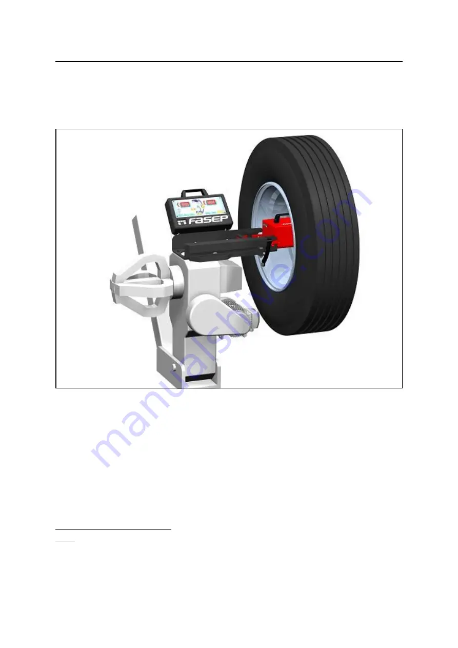
Balatron B150: Manuale dell'Utilizzatore

07 Giugno 2016

per ogni informazione, prego contattare:

www.fasep.it

e-mail:

[email protected]

FASEP 2000 srl
Via Faentina 96
50032 Ronta (Fi) Italy
Tel. #39 055 840 3126
Fax #39 055 840 3354

i

B150.T

BALATRON B150
MANUALE DELL'UTILIZZATORE

Summary of Contents for BALATRON B150

Page 1: ...ll Utilizzatore 07 Giugno 2016 per ogni informazione prego contattare www fasep it e mail vendite fasep it FASEP 2000 srl Via Faentina 96 50032 Ronta Fi Italy Tel 39 055 840 3126 Fax 39 055 840 3354 i...

Page 2: ...a seguito di modifiche non autorizzate sull apparecchio l uso di accessori non originali o non autorizzati vedi lista Accessori in questo manuale per un elenco di accessori originali utilizzabili per...

Page 3: ...are l equilibratrice 4 1 4 2 Come controllare la calibrazione 4 2 5 MISURA E CORREZIONE DELLO SQUILIBRIO 5 1 5 1 Montaggio della ruota sull equilibratrice 5 1 5 2 Inserimento delle dimensioni del cerc...

Page 4: ...tata per utilizzo in ambienti chiusi vedi Appendice Caratteristiche Ambientali PERICOLO Questa macchina progettata per l equilibratura di ruote di veicoli le cui dimensioni e pesi rientrino nel campo...

Page 5: ...NE 2 1 Movimentazione I ATTENZIONE Quando la macchina deve essere mossa non sollevare mai l equilibratrice dall albero o parti vicine 2 2 Assemblaggio della macchina Per facilitare il trasporto l equi...

Page 6: ...ruzione differenziale e magnetotermico tenendo conto delle Specifiche di Alimentazione della Vostra equilibratrice 2 4 3 L allacciamento della macchina deve essere effettuato tramite spina 2 4 4 L equ...

Page 7: ...ni Speciali MODE Selezione modalit di lavoro Dynamica Statica Alu SET Conferma selezione OPER Selezione Operatore 1 o 2 FINE Selezione scala di lettura FUNC Selezione funzioni specifiche START STOP At...

Page 8: ...Montare ruota con flangia e controflangia come fig 12 Accendere l equilibratrice Quando appare SOF X XX versione sw premere SET appare CAL sul display di sinistra Premere SET per entrare nel programm...

Page 9: ...come illustrato in figura 16 Eseguire manualmente il lancio della ruota Premere FINE per visualizzare il valore preciso Il risultato corretto 160 0 3 Quando tutti i led del display di sinistra sono ac...

Page 10: ...ni l attacco filettato e gli accessori prima di montare una ruota sulla macchina PERICOLO Bloccare sempre correttamente le flange sull albero motore e la ruota alla flangia usata 5 1 2 Abbassare l equ...

Page 11: ...due operatori Ognuno pu impostare le misure delle ruote che sta equilibrando senza modificare i dati dell altro semplicemente premendo il tasto OPER Oltre alle misure viene memorizzata anche la modal...

Page 12: ...ati Premere MODE per selezionare la modalit desiderata Selezionare il diametro della ruota Inserire la misura interna IN 1 Inserire la misura esterna IN 2 5 2 4 ALU S 1 ALU S 2 Introduzione automatica...

Page 13: ...della ruota fino a cheGOOD appare sul display G NOTA Acc El imprimere maggiore velocit rEd UCE ridurre la velocit Go od velocit impressa corretta 5 3 2 Alla fine del lancio frenare la ruota I display...

Page 14: ...chio Posizionare la ruota sull albero nella stessa posizione precedente Eseguire manualmente il lancio della ruota Il display di sinistra 20 nell esempio indica lo squilibrio statico presente Il displ...

Page 15: ...UNC per entrare nella funzione di split Girare la ruota fino a che non appare POS 1 Segnare il pneumatico posizionando la prima razza di riferimento a ore 12 Girare la ruota fino a che non appare POS...

Page 16: ...tistica Accendere la macchina e premere SET mentre i display visualizzano SOF X XX Selezionare Sta tis e premere SET per entrare in statistica Le funzioni possibili sono tOt Totale lanci effettuati SU...

Page 17: ...assorbita 5 watt Velocit di rotazione 50 70 rpm Tempo di equilibratura 10 25 s Precisione di misura 20grs carri Dimensioni della ruota Diametro cerchio da 8 200mm a 26 650mm Diametro ruota max 34 870m...

Page 18: ...ale Tecnico Autorizzato 2 Il Pannello di Controllo pu essere rimosso per l assistenza Esso avvitato al corpo macchina mediante viti in modo tale che solo volutamente possa essere rimosso La rimozione...

Page 19: ...enza sulla macchina 10 L assistenza a schede parti elettriche e meccaniche deve essere fatta solo da un Centro Assistenza Autorizzato C Errori e Malfunzionamenti riconosciuti dal Computer Gli errori p...

Page 20: ...B150 User s Manual 07 June 2016 For any information please contact www fasep it e mail export fasep it FASEP 2000 srl Via Faentina 96 50032 Ronta Fi Italy Tel 39 055 840 3126 Fax 39 055 840 3354 i B15...

Page 21: ...ce breakdown accidents due to unauthorized modifications of the unit use of non original or unauthorized accessories see Accessories listing in this manual for a list of original accessories available...

Page 22: ...cer 4 1 4 2 How to control the calibration of Wheel Balancer 4 2 5 MEASUREMENT AND CORRECTION OF UMBALANCE 5 1 5 1 Placing the wheel on the wheel balancer 5 1 5 2 Insert the size wheel rim Truck 5 2 5...

Page 23: ...be purchased separately This unit is designed for indoor use only see Environmental Data appendix for reference CAUTION This unit is designed to spin vehicle wheels only within the range of dimensions...

Page 24: ...ATION 2 1 Moving the unit WARNING When the unit has to be moved never lift balancer by shaft 2 2 Assembling the unit For ease of transportation the wheel balancer might be disassembled into units If n...

Page 25: ...ccordance with the power rating specified on your wheel balancer 2 4 3 Electrical connection of the machine should be by plug connectors 2 4 4 The balancer must be effectively connected to ground The...

Page 26: ...see Special Functions MODE To select balancing type Dynamic Static Alu SET Confirm selection OPER To select Operator 1 or Operator 2 FINE To select reading scale FUNC To select specific functions STAR...

Page 27: ...to calibrate the wheel balancer Place the wheel with flange and counterflange as fig 12 Switch on the wheel balancer When appear SOF X XX version sw press SET appear CAL on the display on the left di...

Page 28: ...n the wheel Put the calibration weight as shown in the picture 12 Hand spin the wheel Press FINE to see actual values 160 0 3 is correct result When all LED left side are lit calibration weight must b...

Page 29: ...es Clean accurately all cones shaft and adappter surface before placing the wheel on the wheel balancer CAUTION Always make sure flanges are correctly locked on the motor shaft and wheel is correctly...

Page 30: ...r can be used from 2 operators in the same time Everyone can memorize the dimensions of the wheel to balance with OPER buttom The machine memorizes the operating procedure too 5 2 1 DYNAMIC MODE Press...

Page 31: ...l imput Press MODE to select the modality desired Select the diameter of the wheel Insert the internal mesure IN 1 Insert the external mesure IN 2 5 2 4 ALU S 1 ALU S 2 Automatic input optional Press...

Page 32: ...n the display NOTE AccEl accelerate speed is too low rEdUCE decelerate speed is too high Good correct speed 5 3 2 At the end of the spin stop the wheel The display will show the weight position and we...

Page 33: ...on the rim After mounting the tyre the wheel must be put on the shaft in the same position as before Hand spin the wheel Left display 24 in example indicates present static umbalance Right display 55...

Page 34: ...press FUNC to enter in the split function Turn the wheel until POS 1 is displayed Mark the tyre when the first spoke selected is at 12 o clock Turn the wheel until POS 2 is displayed Mark the tyre whe...

Page 35: ...e of PS2 Cou Safety cover is open or closed 8 3 Statistic menu Switch on the wheel balancer and press SET before SOF X XX will disappear Select Sta tis and press SET to enter in the statistic menu The...

Page 36: ...wer 5 watt Balancing speed 50 70 rpm Measuring time 10 25 s Measure precision 20grs carri Wheel dimensions Rim Diameter da 8 200mm a 26 650mm Wheel Diameter max 34 870mm Wheel Weight Max 200 Kg 440Lbs...

Page 37: ...herefore restricted to Authorized Service Engineers 2 The Control Panel may be removed for servicing It is secured to the machine body through screws so that only voluntarily it may be removed Removal...

Page 38: ...by an Authorized FASEP 2000 Service Center C Errors and Malfunctions recognized by the Computer Errors may apply to some model only ERR 1 Shaft does not rotate ERR 2 Rotation Direction is wrong ERR 3...

Page 39: ......

Reviews:

Related manuals for BALATRON B150