


Fasep 2000 srl
Rev. 1.1
Balatron B350.G3
10 September 2012
C-1
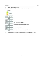
1
The pneumatic system which is home to a machine and which provides the energy for the lifting of the wheel is equipped
with a filter-pressure regulator which prevents any moisture present in the plant upstream from penetrating inside the
circuit of the lift . The regulator prevents the circuit is powered with higher pressures of 8 bar in that it allows a maximum
transfer of this pressure.
2
The valve actuation is a component of security since its release (position 0) stops the movement of the lift.
3
The articulation of the pantograph system is protected against the danger of crushing a metal housing attached with
screws that are not easily removable.
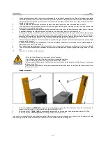
4
The legs are protected from being crushed by the position of the two tracks on the floor that avoid, with their bulk, the shoe
to penetrate beneath the sliding wheel support and then to hold off the legs from the danger zone.
5
The ramp is attached to the sliding wheel support and then rises and falls with it, the connection between the ramp and
the sliding wheel support is constructed with a hinge and this allows the ramp to be free to rise and fall so that the
pressures involved are such that even if an artist less trapped between the ramp and the floor during the descent, it does
not entail any serious consequence. In any case it is recommended the use of safety shoes.
6
The lever that controls the functions of the machine is protected against inadvertent or accidental operation by the handle
located next to the lever.
7
In case of lack of supply of compressed air from the installation General on the machine will not create dangerous
situations as they stop all movements.
8
Were affixed to some pictographs that call attention to some aspects of hazardous debris that involve the use of the lift.
9
The SOUND PRESSURE level at operator's ear resulting from raising and its organs in general is not significant (<70 dB
(A)).
10
There are no vibrations on the operator.
- Using the lift is allowed only to properly trained operators.
- It is forbidden to use the lift in bad conditions or precarious balance.
- It is not allowed to use the lift to operators without Safety shoes.
- Before using the lift ensure the stability of the machine by checking the integrity and effectiveness of anchoring
the base to the floor.
- It is forbidden to modify both safety devices mechanical and pneumatic, in particular the pressure reducer of
the pneumatic circuit.
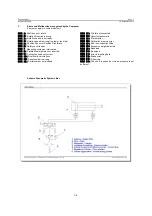
Safety pictograms
1
Label cod. 9M2517
“PERICOLO”
showing care and caution in using the lift, in particular, there are residual risks in
respect of CRUSHING OF THE HANDS, and the CRUSHING FOOT.
2
Label cod. 2M3615
“MAX. 140Kg”
showing that the wheel to be moved must have a maximum weight of 140kg.
3
Label cod. 2M3603
“Working Arrow”
showing positions of the pilot valve.
In case of poor readability or damaged plates applied to the machine, you must rearrange your dealer or the manufacturer's data
plate missing, using the codes provided, and reposition it in the same place the existing one.


