Faro Gage Training Workbook Download Page 70

Basic Training Workbook
Version 1.5 - August 2007

60

Chapter 4: Basic Part Measurements (Metrology Mode)

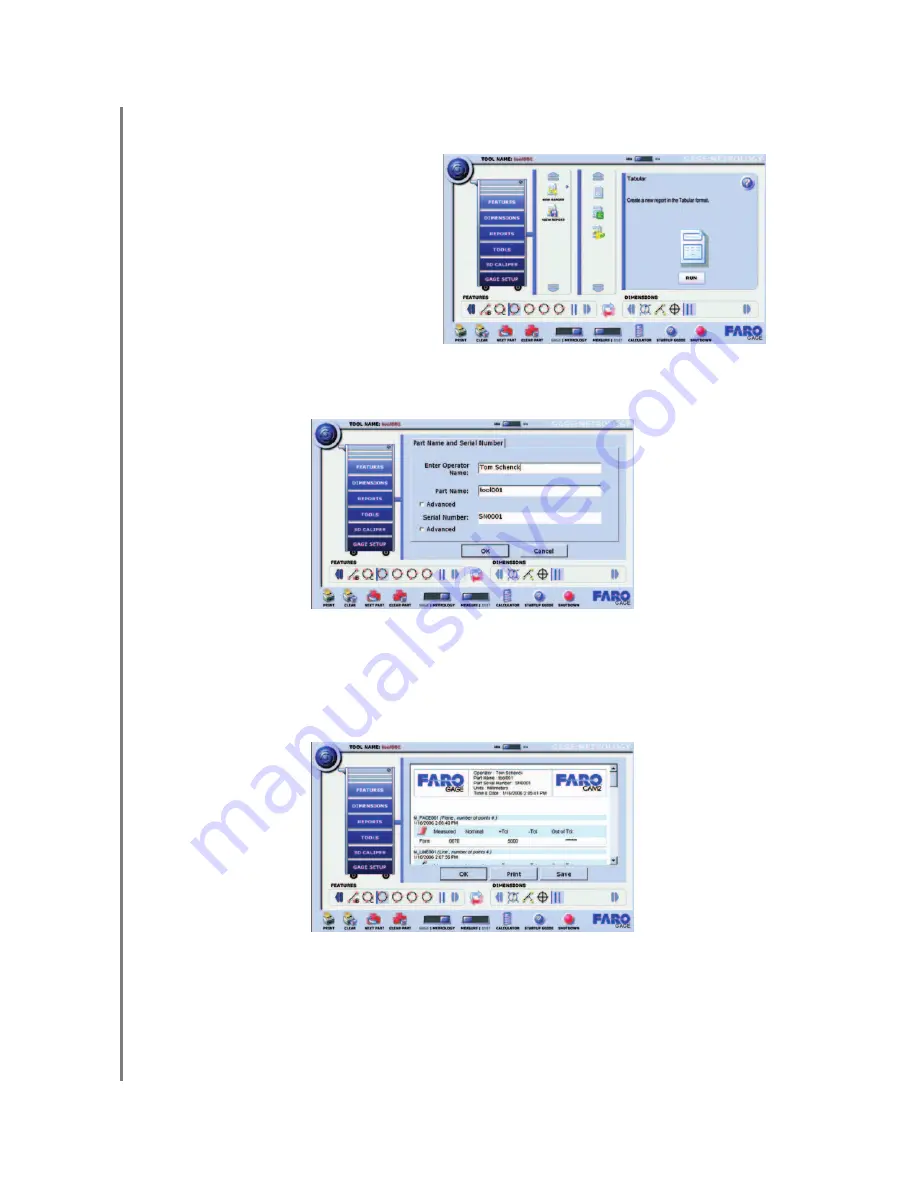
Use the Tabular command to create a report of the features and dimensions on your part.

5

Type your name, the part name, and the serial number, or use the defaults.

N

OTE

:  

Select the ADVANCED check box to choose from existing part names or serial 

numbers.

6

Select OK to generate the report preview.

Select OK to exit the command.

Select PRINT to send the report to any printer connected to your computer.

Select SAVE to create a report file on your computer. You may view and print this 
file later using the View Report command.

1

Select the REPORTS drawer in 
the Toolbox.

2

Select the NEW REPORT 
group.

3

Select the Tabular command.

4

Select the RUN button.

Summary of Contents for Gage

Page 1: ...GAGE TECHNICAL INSTITUTE VERSION 1 5 FARO Gage BASIC TRAINING WORKBOOK STUDENTS BOOK AUGUST 2007...

Page 2: ......

Page 3: ...IN CONNECTION WITH OR ARISING OUT OF THE PURCHASE OR USE OF THE FARO GAGE OR ITS MATERIALS THE SOLE AND EXCLUSIVE LIABILITY TO FARO TECHNOLOGIES INC REGARDLESS OF THE FORM OF ACTION SHALL NOT EXCEED...

Page 4: ......

Page 5: ...e Introduction This course will explain the new and modified commands of FARO Gage Version 1 5 There will be lectures as well as hands on exercises that will allow the student to practice the skills l...

Page 6: ......

Page 7: ...FARO Standard Demonstration Part Plate Remove this page from your workbook and refer to it in the practical exercises to locate the features of the part E 1 2 3 4 5 6 7 8 9 10 F A C D B G P1 P2 P3 P4...

Page 8: ......

Page 9: ...tical Calibration Chapter 2 Basic Measurements Gage Mode Tools Measuring Printing Repeat the Part Practical Using Tools Angle Edge to Edge Distance Hole to Hole Center Geometry Hole Diameter GD T Flat...

Page 10: ...ucibility Table Alignments What is an Alignment Dimensions What is a Dimension Tricky Dimensions Build Commands What is a Build Command Practical Basic Part Measurements Metrology Mode Setting the Ali...

Page 11: ...e mounted in an upright position Do not mount the FARO Gage in an inverted upside down or sideways position To fasten the FARO Gage 1 Attach the 3 5 threaded ring and surface mount plate to any stable...

Page 12: ...ctions before applying power to the computer and the FARO Gage 6 Switch on the FARO Gage and then the Gage computer 7 The FARO Gage software will launch automatically after you have turned on the comp...

Page 13: ...wer on the FARO Gage Arm you must reference the encoders joints The LED in the handle will flash red until the encoders have been cleared Each of the six encoders in the FARO Gage must be referenced b...

Page 14: ...de you create store and run tools on your computer as well as store and print all data for parts that you measure NOTE The FARO Gage software restarts in whichever mode was operating during the previo...

Page 15: ...ems The scroll arrows are dark blue if there are additional items 3 MM IN switch Use the MM IN switch to set the measuring units for your part 4 Command Description There is an icon and a description...

Page 16: ...PART button to repeat the tool list 7 CLEAR TOOLS button Select the CLEAR TOOLS button to erase all tools from the tools list 8 GAGE METROLOGY switch Select the GAGE METROLOGY switch to toggle between...

Page 17: ...Select to generate and print a report All results from previous measurement sessions are kept new results are appended and separated by a header with tool information One report with both previous an...

Page 18: ...pear in color incomplete commands appear grayed out 2 Alignment Tool This tool creates an alignment or coordinate system from previously measured features 3 Dimensions List An icon for each dimension...

Page 19: ...probe is attached the location of the probe tip relative to the Gage s coordinate system must be determined prior to measuring hence the need for probe calibration Calibrate the probe prior to every m...

Page 20: ...robe Calibration cone near the FARO Gage For best results position the calibration cone approximately 2 3 of the Gage arm s reach away from the base 1 Choose Gage Setup Probe Calibration 2 Select the...

Page 21: ...The FARO Gage will collect points as fast as possible scanning until you release the GREEN button 6 Place the ball probe in the hole Start in a vertical position 7 Press and hold the GREEN button Swe...

Page 22: ...then calculated and the probe calibration status is updated If the probe passes then the current date and time is added to the probe information 12 You may view the details for all of the calibration...

Page 23: ...he Tools Drawer The Tools Drawer is available in both GAGE and METROLOGY modes ANGLES Measure angles between features on your part DISTANCE Measure the distance between features on your part GEOMETRY...

Page 24: ...of tolerance You can continue selecting more tools to inspect your part Each new tool will appear in the Tools list 1 The GREEN button is used to take points on the part Green balls spheres illustrate...

Page 25: ...hutting down Gage software erases all active tools and resets your tool list Measurement results are saved automatically You can review your results and print a report using the PRINT button Select th...

Page 26: ...ur part Place the ball probe on the part and digitize points with the GREEN button Digitize 3 or more points on the planar surface Pull away from the part and digitize 1 point with the RED button to c...

Page 27: ...edge Note the direction in which you take the points Pull away from the part and digitize 1 point with the RED button to complete the command 7 Measure another edge on your part Place the ball probe...

Page 28: ...always be the smallest angle based on the positive ends of your measurement direction The last point taken on the edge determines the positive direction Distance Hole to Hole Center Use the Hole to Ho...

Page 29: ...E If any measurement of an individual feature is out of tolerance a RESULTS dialog box appears Select the OK button to continue or select CANCEL to remeasure the feature 6 Measure a hole on your part...

Page 30: ...and digitize points with the GREEN button Digitize 3 or more points on the hole Pull away from the part and digitize 1 point with the RED button to complete the command 8 View the results of your mea...

Page 31: ...ed points 5 Measure a face for the hole The digitized points are projected to the face before the best fit calculation Place the ball probe on the part and digitize points with the GREEN button Digiti...

Page 32: ...nd digitize points with the GREEN button Digitize 3 or more points on the hole Pull away from the part and digitize 1 point with the RED button to complete the command 7 View the results of your measu...

Page 33: ...form deviation of a face 5 Measure a face on your part Place the ball probe on the part and digitize points with the GREEN button Digitize 3 or more points on the planar surface Pull away from the pa...

Page 34: ...button to repeat the tool list This command will automatically prompt you to remeasure all the tools in your tool list Select the PRINT button to print a report of your part 3D Caliper The FARO Gage 3...

Page 35: ...face you want to measure Avoid the following positions You may set the 3D Caliper compensation to either manual setting Towards the base face or Away from the base face Manual compensation allows you...

Page 36: ...or Z base face and measure base face table 3 After setting the base face place the FARO Gage probe on top of your part Look at the screen to see the height from the base face to the surface 4 Press t...

Page 37: ...manually compensate when the surface faces the base face 3D Caliper Temporary Zero You can set a temporary zero with the 3D Caliper to measure relative distances 1 Touch your part at the temporary zer...

Page 38: ...hapter 2 Basic Measurements Gage Mode NOTE Pressing the GREEN button to freeze and unfreeze the display is optional Press and Hold the RED button to clear the temporary zero height You can repeat thes...

Page 39: ...tains all the commands to measure the individual faces holes edges etc of a part After measuring the individual features you can use the Dimensions commands to calculate distances and angles between t...

Page 40: ...FEATURES menu you will be prompted to select a base face You will always need to select the face to which the points will be projected NOTE Gage software will automatically add the prefix M_ to all m...

Page 41: ...rement best fits a face using digitized points Make sure you re in Metrology Mode select the Metrology switch and select OK 4 Type a name for your measured face or use the default name If this face is...

Page 42: ...ton Digitize 3 or more points on the planar surface Pull away from the part and digitize 1 point with the RED button to complete the command 7 View the results of your measurement in the RESULTS dialo...

Page 43: ...igitized points 5 Type a name for your measured edge or use the default name 6 Choose the previously measured face for the edge The digitized points are projected to the face before the best fit calcu...

Page 44: ...s with the GREEN button Digitize 2 or more points on the Edge Note the direction in which you take the points Pull away from the part and digitize 1 point with the RED button to complete the command 9...

Page 45: ...through digitized points 4 Type a name for your measured face or use the default name 5 Choose the previously measured face for the hole The digitized points are projected to the face before the best...

Page 46: ...oints with the GREEN button Digitize 3 or more points in the hole Pull away from the hole edge and digitize 1 point with the RED button to complete the command 8 View the results of your measurement i...

Page 47: ...e through digitized points 4 Type a name for your measured cone or use the default name If this cone is a datum of your part select the DATUM check box 5 Select OK to measure the cone 6 Measure the co...

Page 48: ...for the cone 9 Select OK to add the cone to your FARO Gage part file 10 When prompted to measure the next cone select CANCEL Review Results Select any FEATURE icon from the Features List to review the...

Page 49: ...values that are listed on the design print for your part The Dimensions commands are organized into the ANGLE LENGTH GD T DRO BUILD HOLE BUILD EDGE BUILD FACE and BUILD POINT groups within the Dimens...

Page 50: ...Basic Training Workbook Version 1 5 August 2007 40 Chapter 4 Basic Part Measurements Metrology Mode Feature Reducibility Table Plane Line Point Arc Circle Cylinder Cone Ellipse Line Plane Point...

Page 51: ...e the measured part to the design data If you are tolerancing the location of features X Y Z you must build an alignment The alignment is also known as the X Y Z coordinate system of your part and ref...

Page 52: ...re define the face as the XY plane the edge as the X axis and the center of the hole as the origin or 0 0 0 point of the coordinate system Face Edge Edge If you have measured a face and two edges the...

Page 53: ...res There are several types of dimensions available in FARO Gage such as 1 Length Displays the 3D distance between two features as well as the change in X Y and Z 2 Angle Displays the angle between tw...

Page 54: ...sing Edge to Edge Face to Face This gives the minimum distance between two features The length is measured from the center point of one feature to the perpendicular distance of the other feature Selec...

Page 55: ...pecified on a drawing but do not actually exist on the part such as the intersection of two lines where the corner has a fillet or radius There are several types of build commands in FARO Gage such as...

Page 56: ...ED THIS DRAWING IS CONFIDENTIAL AND MAY NOT BE MADE PUBLIC OR REPRODUCED WITHOUT THE EXPRESS PERMISSION OF FARO TECHNOLOGIES INCORPORATED THIS DRAWING IS LOANED SUBJECT TO RETURN UPON DEMAND AND SHALL...

Page 57: ...0 0 0 origin 7 Type a name for your measured face or use the default name 8 Select the DATUM check box and choose A 9 Select OK to measure the face 10 Measure the face with the FARO Gage Place the bal...

Page 58: ...the RESULTS dialog box 12 Select OK to add the face to your FARO Gage part file This will be your XY plane Z axis 13 Select the CANCEL button to exit the command 17 Type a name for your measured edge...

Page 59: ...igitize points with the GREEN button Digitize 2 or more points on the edge Note the direction in which you take the points Pull away from the part and digitize 1 point with the RED button to complete...

Page 60: ...the default name 28 Choose the previously measured face for the hole The digitized points are projected to the face before the best fit calculation 29 Select the DATUM check box and choose C 30 Select...

Page 61: ...int with the RED button to complete the command 32 View the results of your measurement in the RESULTS dialog box 33 Type Nominal diameter 100 and Tolerance 0 25 0 10 34 Select OK to add the hole to y...

Page 62: ...complete the alignment NOTE The alignment icon will now display a red and blue arrow indicating that an alignment is present The face determines the XY plane and Z axis orientation the edge determine...

Page 63: ...e X Y Z readings as you move the probe around the part Select CLOSE to exit 3D Caliper Inspecting the Part Let s now check the part using the part print on page 46 and the pre established alignment 3...

Page 64: ...FARO Gage Place the ball probe on the part and digitize points with the GREEN button Digitize 3 or more points in the hole Pull away from the hole edge and digitize 1 point with the RED button to com...

Page 65: ...your print or reference guide to make them easier to identify later After you have measured a feature you may edit the cooresponding label by choosing the feature from the list then selecting EDIT Onc...

Page 66: ...features and or dimensions The Best Fit command builds a best fit hole from existing features and or dimensions The points project to the face before the best fit calculation starts 5 Type a name for...

Page 67: ...ircle and Datum Edge B Use the Point To Edge command to build a length between a point and an edge The length is the distance from the point to the edge 5 Type a name for your dimension or use the def...

Page 68: ...RO Gage part file GD T Optional Let s check the Position of the 20mm holes Use the Position command to measure the GD T Position of an existing feature Position measures a feature RFS Regardless of Fe...

Page 69: ...of Feature Size 9 Select the MMC tolerance field and type Position Tolerance 1 0 10 Select OK to review the results 11 Select OK to add the dimension to your FARO Gage part file Review Results and Rep...

Page 70: ...the ADVANCED check box to choose from existing part names or serial numbers 6 Select OK to generate the report preview Select OK to exit the command Select PRINT to send the report to any printer con...

Page 71: ...corresponding part name and serial number for the reported part Choosing the SPC report will generate a file called spcout csv Every report you generate using the SPC option will append to this file T...

Page 72: ...see the names of the pictures in a list 7 Select the OK button to save the tool Load Custom Tool Use the Load command to open a saved tool for your part You will have the option to save any existing t...

Page 73: ...ct the OK button to load the tool Run Custom Tool Use the Run command to reset a saved tool to the beginning which will take you through the measurement routine to measure another part 1 Select the TO...

Page 74: ......

Page 75: ......

Page 76: ...support faro com Telephone Number 800 736 2771 For Sales Inquiries Electronic Product Catalog on www faro com E mail info faro com Telephone Number 800 736 0234 extension 2265 For Training or Technic...

Reviews: