background image


91 

ID 

Alarm text 

Possible cause  

Possible remedy 

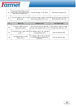
621 

Not available for this product no 
dataset. 

A calibration test has not yet been 
performed for the product in question. 

Perform a calibration test before 
working with the product. 

622 

 The sowing test button is activated. 

The sowing test button was activated 
before opening the calibration screen. 

 Release the sowing test button. 

630 

 Connection lost. 

The connection to the MRC module 
has been lost. 

 Check the cables. 

631 

 Undefined module index. 

 A software error has occurred.  

 Contact customer service. 

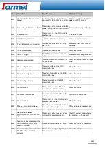
636 

 There is no seed for overdosing. 

Too little seed was detected during 
pre-dosing.  

Make sure that sufficient seed is 
available. 

638 

The engine stopped. 

The MRC engine stopped. 

Check the cables. 

639 

Current too high. 

The MRC motor requires too much 
current. 

Make sure something is blocked. 

640 

No speed was reached. 

The MRC module did not reach the 
required speed. 

Check the cables. Check the seed 
drills. 

641 

Power voltage too low. 

The power voltage of the MRC 
module is too low. 

Check the cables. 

642 

Electronics voltage too low. 

The electronics voltage at the MRC 
module is too low. 

Check the cables. 

643 

Sensor voltage too low. 

The sensor voltage at the MRC 
module is too low. 

Check the cables. 

650 

Connection lost. 

The connection to the 

AIRidium® 

sensor has been disconnected. 

Check the cables. 

651 

Undefined module index. 

An error occurred of the 

AIRidium® 

module. 

Contact customer service. 

660 

Connection lost. 

The connection to the CAN Repeater 
has been disconnected. 

Check the cables. 

663 

Drop below minimum voltage. 

The voltage is lower than the pre-set 
minimum supply voltage. 

Check wiring and supply voltage. 

664 

Sensor error detected 
PLANTirium®. Pollution rate too 
high. 

The sensor is dirty. Sensitivity does 
not match the selected product. 

Clean the sensor and/or change 
the sensitivity in the product. 

665 

An error has been detected in the 
PLANTirium® sensor. Faulty 
sensor transmitter. 

The sensor transmitter is defective. 

Check the cables on the sensor. 

666 

An error has been detected in the 
PLANTirium® sensor. Not 
achieved. 

The minimum supply voltage has not 
been reached. 

Check the cables. 

Summary of Contents for FALCON PRO

Page 1: ...31 DI CZ46504931 Farmet a s Ji inkov 276 552 03 esk Skalice CZ telefon 420 491 450 111 fax 420 491 450 136 GSM 420 774 715 738 OPERATING INSTRUCTION Falcon PRO OPERATING INSTRUCTIONS SN 2021 0123 VIN...

Page 2: ...agriculture and food industry in many markets around the world Our own products and technologies are created in close cooperation between Farmet specialists and end customers research institutions an...

Page 3: ...2 AGRICULTURAL MACHINES OIL FEED TECH...

Page 4: ...plate and on the machine frame This machine serial number must always be stated when ordering service or spare parts The type plate is located on the front of the hopper Machine equipment V1 small fan...

Page 5: ...Selecting and setting up the virtual terminal VT and task manager TC 23 11 MACHINE FAN 24 FAN WITH SEPARATE DRIVE ON PTO 26 FAN SPEED SETTING ACCORDING TO SEED 27 12 SEED SWITCHING SENSORS 28 SOWING...

Page 6: ...ure wheel trowels 69 17 3 2 Pressure wheel 70 17 3 3 Harrows 71 18 ADJUSTIN THE DOSE DURING WORK 72 19 EMPTYING THE HOPPER USING ELECTRONICS 73 20 WORKING POSITION SOURCE 74 21 SOURCE SPEED MACHINERY...

Page 7: ...6 31 SHUTTING DOWN THE MACHINE 100 32 ENVIRONMENTAL PROTECTION 100 33 END OF LIFE MACHINE DISPOSAL 100 34 SERVICE AND WARRANTY CONDITIONS 100 SERVICE FAVOR 100 GUARANTEE 100...

Page 8: ...itch 8 Check that the seed drill is clean 55 9 Check the squeegee for leaks in the seed drill 55 10 Check the permeability of the seed hoses 11 Sprinkle the seed 37 12 Adjust the machine plane and loc...

Page 9: ...re kg 50 120 50 120 Disc diameter of the double disc coulter 355 355 Number of preparation section disks 490 Front row 12 16 Back row 11 15 Number of chisels 3 row section depth 80 mm spacing 100 mm 1...

Page 10: ...quirement 12 V DC 40 A 12 V DC 40 A Tractor hitch requirement TBZ cat 3 TBZ cat 3 Machine weight kg 3 800 4 400 Transport Brake system Observe the national regulations applicable to the transport of m...

Page 11: ...with the machine He must be familiar with the machine instructions and the machine operator They must know the meaning of the safety signs placed on the machine Respecting them is important for safe a...

Page 12: ...ties If the operator must consume a pills prescribed by a doctor or consuming free pills for sale must be informed by a doctor that in these circumstances is capable to work responsibly and safely ope...

Page 13: ...rements of the machine have to be careful and considered on the others drivers on the public roads The operator must be sure to secure rear arms TBZ of the tractor and put them in secure position when...

Page 14: ...ipulation with the machine ready the instructions for using When operating follow the instructions and safety regulations for operating the machine P 1 H 2 Driving and transporting the machine structu...

Page 15: ...out of reach when unfolding the service platform P 20 H 11 Keep safe distance from electrical equipment when working or transporting the machine P 39 H 12 It is forbidden to fold and unfold the side...

Page 16: ...tributor head number 1 for dispenser 1 15 Exchange preparatory section 8 Targets with road lighting 16 Flexi board 14 5 1 4 7 1 9 8 3 1 2 1 6 10 11 13 12 15 1 Nastaven Z sobn ku 1 motor 1 4 P edstih v...

Page 17: ...nt for the machine FALCON 3 90 kW Tractor engine power requirement for the machine FALCON 4 117 kW Requirement for TBZ tractor Spacing of lower suspension joints measured on joint axels 1010 1 5 mm ca...

Page 18: ...ine to the hydraulic circuits of the tractor according to the table below To prevent involuntary or any stranger mistaken hydraulics movement the control cabinets on the tractor must be secured or loc...

Page 19: ...18 Hydraulic diagram of the machine Markers Tramline markers Preparation section Fertilization Folding Tipping machine...

Page 20: ...ce where it will not obstruct the driver s view and at the same time be in the operator s field of vision Secure the wiring securely to prevent mechanical or thermal damage To connection cable set con...

Page 21: ...to the ignition of the tractor or to the switched 12 V voltage 12 V switched by the key or switch 1 Terminal 6 Fuse 50 A 2 Positive battery pole 7 ISO socket 3 Negative battery pole 8 Fuse 1 A 4 Volt...

Page 22: ...al and connect to the IN CAB socket of the tractor and connect the terminal For this use it is necessary to set the terminal as VT1 you can read this in the chapter VT a TC settings page 23 ME Termina...

Page 23: ...tor settings The machine application is loaded in the tractor ISOBUS application after 2 5 minutes communication between the tractor and the machine must take place first Data cable Tractor ISOBUS soc...

Page 24: ...inal you want to use VT for example Mueller or another terminal For the basic terminal it is necessary to select in the settings that it also work as a secondary terminal 3 Select which task manager y...

Page 25: ...apacity per revolution 8 cm3 rev Small fan Maximum speed 5500 rev min Minimum speed 1000 rev min Pressure branch P Minimum pressure in the pressure hose 130 bar Maximum pressure flow in the pressure h...

Page 26: ...or damage to the hydraulic drive or tractor caused by incorrect connection of the hydraulic drive 1 Fan hydraulic motor 4 Quick coupler of tractor switchboard 2 Waste branch ISO 20 T 5 Pressure hose I...

Page 27: ...t the hydraulic generator 3 to the tractor PTO 2 Set the working speed on the tractor 540 rev min 3 Use the reducing valve 8 to set the required fan speed 4 Check the speed on the machine monitor 1 Ge...

Page 28: ...ting according to seed Falcon Compact 3 Falcon Compact 4 V1 Crop Speed of fan Grain 4000 5500 Legumes 4000 5500 Pea 5000 5700 Rape 2500 2700 Clover 3000 3500 Grass 3000 3500 See page 3 for your machin...

Page 29: ...at which the sowing is switched on depends on the position of the sensor set between the seed frame and the main machine frame If the seed section frame is in the upper position the sensor must be in...

Page 30: ...rkers obstacle swamp 17 Speed of fan 8 Settings 18 Travel speed of the machine 9 Control of hydraulic functions of the machine 19 Dispenser dose information 1 2 3 10 Sowing rate correction Beacon is a...

Page 31: ...ich the computer is turned on Total hours Period time which the machine was working for Total distance Worked distance Total area Worked area Area performance Applied area per hour Creating a task wit...

Page 32: ...w much work can still be done with the remaining contents of the hopper 1 On the working screen Leftover amount Remaining sum in the hopper Leftover area Area where you can still work with the remaini...

Page 33: ...when unfolding in the hall For service purposes of the machine in the hall it is necessary to set the simulated speed to 0 km h when unfolding the machine in the hall 1 Turn off the application 2 3 Se...

Page 34: ...and they are hydraulically tiltable The distance of engagement of the marker disc is always measured from the center of the seed coulter The markers must be set to the correct length in the field The...

Page 35: ...essivity of the markers depending on the soil conditions 1 Loosen the hexagonal screws 1 2 Adjust the marker and retighten the hexagonal screws 3 Check the quality of the work of the markers and adjus...

Page 36: ...t at the same time as the sowing section Function icon Meaning Control of the left marker only Deactivate marker control Obstacle function the hydraulics only control the marker without the rear sowin...

Page 37: ...y pressure to 6 Detour the obstacle and then apply pressure 7 Deactivation of an obstacle 13 6 4 Swamp function The swamp function is used to raise the sowing section without cancelling the sowing 1 T...

Page 38: ...ssary for the correct operation of the machine 1 Current residual amount in the hopper 3 Maximum filling of the tank 2 Write the quantity poured into the hopper here 4 Resetting the state in the hoppe...

Page 39: ...1x press by 10 2x press by 20 Gear ratio If there is a gear behind the outlet shaft motor it must be entered here The motor shaft speed is entered first and then the metering unit speed Example 2 rev...

Page 40: ...39 Assignment of the motor to the given hopper 1 Shutting down the application 2 1 Settings of hopper 1 motor 1 2 Assigned product from the product database 1 2 Touch Basic...

Page 41: ...rk sowing with one metering unit deactivation of fertilization 1 Settings 2 Select the product dispenser that you want to deactivate by pressing on its name MOTOR 1 3 Deactivation Activation 4 This sh...

Page 42: ...41 Seed flow sensing Dickey John deactivation 1 Shutting down the application 2 3 4 5 Seed flow sensing deactivated 6 To reactivate the sensors select YES Touch Basic...

Page 43: ...returning to the field This function is only available when the machine is stopped and not in the working position Deactivation the automatic addition of trips If the tramline counting is stopped the...

Page 44: ...2 Odd result Odd tramline rhythms 15 2 2 3 Decimal results Special tramline rhythms 15 2 3 Types of valves placement on the machine TYPE A One valve on each side of the machine OR TYPE B One valve on...

Page 45: ...valves are on one side of the machine Example Creating a tramline on both sides of the machine at the same time Creating a tramline in one run TYPE A Possible valve positions Result of the calculatio...

Page 46: ...s Right valves 2 2L 2 2 1 4 4L 4 3 2 6 6L 6 4 3 8 8L 8 5 4 10 10L 10 6 5 12 12L 12 7 6 14 14L 14 8 7 Start sowing from the right side of the TYPE B field Possible valve positions Result of the calcula...

Page 47: ...calculation RhNo The resulting rhythm Left valves Right valves 2 999 2 1 4 999 4 2 6 999 6 3 Start of sowing from the right side of the field individual rhythm TYPE C E Possible valve positions Result...

Page 48: ...of the machine Example Creating a tramline one in one run Creating a tramline in one run TYPE A Possible valve positions Result of the calculation RhNo The resulting rhythm Left valves Right valves 3...

Page 49: ...e other side of the machine Example Creating a tramline with a special rhythm Start of sowing from the left side of the TYPE C D E field Possible valve positions Result of the calculation RhNo The res...

Page 50: ...67 63L 14 3 12 7 8 5 33 24 16 9 8 14 3 5 5 65L 22 14 9 3 20 6 67 64L 20 10 11 4 17 7 5 30 30 27 4 19 12 9 33 999 28 14 15 5 24 Start of sowing from the right side of the field TYPE C D E Possible val...

Page 51: ...hNo The resulting rhythm Left valves Right valves 2 67 62R 8 7 2 5 4 3 33 21 10 6 5 9 2 3 5 29 14 9 6 13 2 4 5 19 18 12 7 16 3 4 67 63R 14 7 8 3 12 5 33 25 16 14 3 9 8 5 5 65R 22 3 20 14 9 6 67 64R 20...

Page 52: ...the rhythm of the tramlines follows from the graphic representation and the table Grip of the machine m Grip of the sprayer m Program Number of line Number of rides per machine width length Left Righ...

Page 53: ...here in the entire system The pressure reducing valve must be set to 0 2 MPA Check the valve drip tray When the valve is running the red signal light on the switchboard must always be on 1 Compressed...

Page 54: ...is located on the seed drill head holder 1 Slide out upwards the valve adjustment segment 2 Tighten to add pressure 3 Release to reduce pressure 4 After setting the required pressure of 0 2 MPA slide...

Page 55: ...54 Tramline markers The tramline markers are automatically controlled together with the tramline valves The tramline markers can be deactivated using the ball valve on the rear target holder...

Page 56: ...ing a new part The trowel must extend 1 2mm beyond the edge of the circular opening of the dispenser Before each use while standing it is necessary to check the cleanliness of the roller and the dispe...

Page 57: ...in the roller between the metering discs and the spacer roller disassemble and clean the roller Rough seeds For sowing rough seeds corn beans peas etc it is necessary to adjust the metering unit The d...

Page 58: ...roller Keep the washers 4 on both sides of the roller 7 Secure the roller 3 with secure rings 2 8 Insert the roller 3 into the dispenser 9 Replace the side cover 1 and tighten the screws 6 10 Secure...

Page 59: ...9 cm When sowing only the metering discs in the roller rotate The spacer cylinders are blocked stops on the housing When assembling and disassembling the rollers the screws 2 must be turned into the...

Page 60: ...of hose distribution See page 3 for your machine configuration Hose distribution type EC Hose distribution type HM 100kg ha 1 2 1 2 1 2 1 2 100kg ha 50kg ha 50kg ha 125 150mm 100kg ha 100kg ha L P 10...

Page 61: ...4 Turn on the application 5 Settings 6 Select the Product for which you want to calibrate Type of hose distribution EC setting up MOTOR 1 2 3 Type hose distribution HM setting up SEED FERTILIZER 7 Ca...

Page 62: ...ation button 20 Hold down the calibration button There must be a large amount of seed in the bucket for accurate calibration Example Wheat 4 kg Rape 0 5 kg 21 After releasing the calibration button we...

Page 63: ...5 km h kg ha min 6 12 4 5 9 3 6 2 3 4 5 2 4 Corn kg ha max 24 48 18 36 12 24 9 18 8 16 V40 5 15 km h kg ha min 13 26 10 20 7 13 5 10 4 9 Grain corn spelled without chaff kg ha max 50 100 38 75 25 50 1...

Page 64: ...8 0 5 0 81 0 79 0 6 0 65 0 4 0 8 0 36 0 22 V3 5 3 5 2 2 1 3 1 1 V7 7 4 5 3 6 3 2 V18 18 10 8 5 V20 20 16 V40 40 31 30 27 20 32 32 V100 100 77 74 68 50 81 79 V250 250 193 185 170 125 203 198 V500 500 3...

Page 65: ...nk 1 Each hole corresponds to a certain sowing depth This only applies when the machine is level 1 Metal plate with scale from 1 to 9 2 Depth adjustment pin 3 The pull of the backdrop The values in th...

Page 66: ...ecommended sowing rate Spring wheat 4 5 cm 220 kg Spring triticale 4 cm 200 kg Spring barley 3 5 cm 200 kg Oat 3 5 cm 200 kg Corn 5 8 cm 20 70 kg Buckwheat 3 5 cm 70 kg Peas 4 6 cm 250 300 kg Spring w...

Page 67: ...depth in the field after each change of coulter pressure or sowing depth 1 Lower the machine to the working position drive a few meters 2 Check the required seed placement depth and seedbed compaction...

Page 68: ...he wheel to gradually tighten the pressure reducing valve to increase the coulter pressure 3 Again drive a few meters and check the seed placement depth 17 2 2 Lowering the pressure 1 For lowering the...

Page 69: ...ngth and the formation of a groove for seed placement Disk adjustment In case of wear the seed discs it is necessary to adjust the distance between the discs by changing the location of the spacers Al...

Page 70: ...and pressure wheels Regularly check the function and wear of the trowels Disc trowels The trowel has a carbide tip the edges Make sure that the entire trowel rests evenly on the surface of the disc P...

Page 71: ...ust the position of the pressure wheel relative to the coulter disc If you want to have a different sowing depth between neighbour rows you must change the position of the link wheel Example On seed c...

Page 72: ...of the harrows by adjusting the pin With a large amount crop residues harrows can be discarded 1 1 Discarded harrow 2 The first degree of aggression of the harrow 3 The second degree of aggression of...

Page 73: ...djustment 3 OR 4 On the work screen the change is shown as follows The control unit recalculates the target dose After one minute of working with the changed target dose the change indicator starts fl...

Page 74: ...the application 2 3 It is necessary to have a selected container that we want to empty Hopper 1 2 3 4 5 Confirm Dispenser 6 7 The calibration buttons are currently used to empty the hopper When using...

Page 75: ...pplication 2 Settings 3 Go to the next page 4 Go to the next page 5 Working position Working position sensor 1 The source is the machines antenna sensor default setting Tractor The source is the worki...

Page 76: ...SOBUS or CAN of the tractor 2 Work equipment The source of speed is radar or speed GPS directly on the machine If the machine is equipped with radar set the number of pulses to 13 500 to 100 meters If...

Page 77: ...s be negative sowing section if the section is in front of the axle the value must be positive fertilization section The button is used to move to the setting of arm 2 3 and connection 1 Use the back...

Page 78: ...lighting 1 2 After activating your selected function use to return to the work screen Function icon Meaning Switching work lights on and off Switching the hopper lighting on and off Switching the beac...

Page 79: ...g the left half of the machine on and off motor 1 Switching the right half of the machine on and off motor 2 Switching off sections from the left side Switching sections from right to left Switching o...

Page 80: ...3 It there is a few post harvested residues in the field this harrow is set to a steep position on the contrary if there are many post harvested residues in the field such as sowing corn the harrow m...

Page 81: ...controlled with help and an open ball valve 1 Piston rod for section depth adjustment 2 Front preparation section disc 3 Flexi board section The red clip at the disc section must never be removed The...

Page 82: ...or track cultivators All Falcon machines with a disc pre processing section are equipped with tractor track cultivator to loosen the tractor tracks Depth setting of cultivators Loosen the screws 1 Adj...

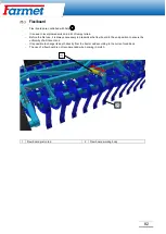
Page 83: ...is always necessary to pressurize the flexi board to the end position to ensure the uniformity of all its sections It is possible to change its depth directly from the tractor cab according to the cur...

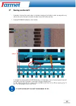
Page 84: ...ng STANDARD fertilization in the interline To readjust the sowing section to STRIP technology it is necessary to move the sowing section by half the spacing of the seed coulters A This is done using t...

Page 85: ...e the locking segment from the whole section 2 All section displacement pins must be lubricated 3 Insert the screw for moving the section accessory 4 From the left side we will gradually start moving...

Page 86: ...n a crane For hanging it necessary to use fabric or rubber harnesses with sufficient load capacity There is a risk of damaging the machine when using the chain Suspension point on the drawbar Suspensi...

Page 87: ...job is activated in the ISOBUS TC application The job is activated in the ISOBUS TC application Deactivate the order 009 Speed signal lost from CAN bus The cable connection has been disconnected Check...

Page 88: ...oduct Choose another dataset or perform a calibration test for the selected product 046 Loop overflow There is a conflict between the database and the machine You need to free up disc space on the ter...

Page 89: ...en reached Excavate the sowing section The machine is not in the working position Excavate the sowing section 406 Dosing was stopped because the machine was not completely raised Excavate the sowing s...

Page 90: ...rpm ID Alarm text Possible cause Possible remedy 416 The blower rotates too slowly Dosing was stopped The current fan speed is lower than the value of the parameter Min rpm Increase the fan speed or c...

Page 91: ...tem did not detect any seed flow Check the seed flow system 609 Seed flow was detected Seed flow occurred in the tramline Check the tramline switching Kalpak tightness check 611 Low tank level There i...

Page 92: ...e too low The power voltage of the MRC module is too low Check the cables 642 Electronics voltage too low The electronics voltage at the MRC module is too low Check the cables 643 Sensor voltage too l...

Page 93: ...dex An unconfigured monitoring control module was found Check the number of configured or connected modules 685 An error been detected in the control module Voltage drop module error It is necessary t...

Page 94: ...s been detected in the CAN repeater Error converting AD The CAN Repeater is defective Contact the customer service 696 An error has been detected in the CAN repeater Error entering address An error wa...

Page 95: ...table places When adjusting cleaning maintaining and repairing the machine you must secure those parts of the machine that could endanger the operator by falling or other movement Repairs to the hydra...

Page 96: ...s bearings electrical and electronic parts with a high pressure cleaner or a direct stream of water Seals and bearings are not waterproof at high pressure Hydraulic system Check the function tightness...

Page 97: ...18 x 1 5 300 Nm M 20 x 1 5 400 Nm M 22 x 1 5 500 Nm X X Brake system Brake lines and hoses check function tightness fastening and clamping or breakage X X Brake components check function tightness fas...

Page 98: ...se mixer Tightness clamping points clogging general condition X X Hydraulic couplings and hoses Tightness of all components and permeability X Distributor Foreign matter control Unscrew the distributo...

Page 99: ...reeze approx 0 1l without ethanol use the one recommended by the tractor manufacturer Secure the machine against movement with wheel chocks Release the parking brake bleed the air and close the brake...

Page 100: ...wheels axles M24 8 8 710Nm Tray screws Hydraulic air connections M16x1 5 60Nm Hydraulic fittings air fittings M22x1 5 140Nm Hydraulic fittings air fittings Load of an empty machine on axle Tire from...

Page 101: ...e applicable waste laws 34 Service and warranty conditions Service favor Service is provided by a sales representative after consultation with the manufacturer or the manufacturer directly Spare parts...

Page 102: ...ber Fabriknummer n de production numer produkcyjny 3 P slu n na zen vl dy 176 2008 Sb sm rnice 2006 42 ES Applicable Governmental Decrees and Orders No 176 2008 Sb Directive 2006 42 ES Einschl gige Re...

Reviews: