background image

Parts Identification - Teleswing

68

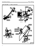
WHEEL DRIVE

21

4

6

16

8

24

25 5

6

9

17

12

19

10

2

3

13

11

18

2

3

22

14

20

15

23

7

1

931725

Summary of Contents for 13''

Page 1: ...092018 F2426 OPERATOR AND PARTS MANUAL TELESWING AUGER Model 13 16 ...

Page 2: ......

Page 3: ...IONS 87 WARRANTY 93 Manufacturer s Statement For technical reasons Farm King reserves the right to modify machinery design and specifications provided herein without any preliminary notice Information provided herein is of descriptive nature Performance quality may depend on soil fertility applied agricultural techniques weather conditions and other factors ...

Page 4: ... Teleswing 2 ...

Page 5: ...ngTurns Freely Gear Box Oil Level Checked All Fasteners AreTight Machine Is Lubricated CheckTire Pressure All Lights And Reflectors Installed All Lights And Reflectors Cleaned And Working All Decals Installed Guards And Shields Installed And Secure Review Operating And Safety Instructions Check For Hydraulic Leaks Date Dealer Rep Signature The above equipment and Operator And Parts Manual have bee...

Page 6: ...Warranty Registration Form Teleswing 4 ...

Page 7: ...tification of the Farm King equipment READ AND UNDERSTAND THIS OPERATOR AND PARTS MANUAL BEFORE OPERATING YOUR FARM KING EQUIPMENT If you have any questions see your Farm King dealer This manual may illustrate options and accessories not installed on your Farm King equipment OWNER S INFORMATION 7 Serial Number Location 7 EQUIPMENT IDENTIFICATION 8 Component Location 8 ...

Page 8: ...Introduction Teleswing 6 ...

Page 9: ...re the accuracy of this publication Farm King makes no warranty or guarantee of any kind written or expressed implied or otherwise with regard to the information contained within this manual Farm King assumes no responsibility for any errors that may appear in this manual and shall not be liable under any circumstances for incidental consequential or punitive damages in connection with or arising ...

Page 10: ...8 EQUIPMENT IDENTIFICATION Component Location CHAIN BOX COLLECTOR COLLECTOR PIVOT BRAKE MOTOR ENERGY CHAIN RETRACTOR WHEEL DRIVE MOTOR DRIVE WHEEL TILT CYLINDER ROLLING WHEEL HOPPER TRANSITION INSPECTION COVER HYDRAULIC VALVE ...

Page 11: ...ator 11 Use Safety Rules 12 Safety Rules For PowerTake Off PTO Driven Equipment 12 Machine Requirements And Capabilities 13 Transport Safety 13 FIRE PREVENTION 14 Maintenance 14 Operation 14 Fire Extinguishers 14 Electrical 14 Hydraulic System 14 Fueling 14 Welding And Grinding 14 EQUIPMENT SAFETY SIGNS DECALS 16 SAFETY SIGN OFF FORM 19 ...

Page 12: ...Safety Teleswing 10 ...

Page 13: ... working An operator who is taking prescription drugs must get medical advice to determine if he or she can safely operate a machine and the equipment Understand the written instructions rules and regulations The written instructions from Farm King include the Warranty Registration Dealer Inspection Report Operator And Parts Manual and machine signs decals Check the rules and regulations at your l...

Page 14: ... clear of bystanders especially small children DO NOT permit personnel to be in the work area when operating the equipment The equipment must be used ONLY on approved tractors transport vehicles DO NOT modify the equipment in any way Unauthorized modification may impair the function and or safety and could affect the life of the equipment DO NOT make any adjustments or repairs on the equipment whi...

Page 15: ...ks underneath and support the equipment securely before working under raised equipment Keep bystanders clear of moving parts and the work area Keep children away Use increased caution on slopes and near banks and ditches to prevent overturn Make certain that the Slow Moving Vehicle SMV emblem is installed so that it is visible and legible When transporting the equipment use the flashing warning li...

Page 16: ...cal Check all electrical wiring and connections for damage Keep the battery terminals clean and tight Repair or replace any damaged part or wires that are loose or frayed Battery gas can explode and cause serious injury Do not jump start or charge a frozen or damaged battery Keep any open flames or sparks away from batteries Do not smoke in battery charging area Hydraulic System Check hydraulic tu...

Page 17: ...Safety Teleswing 15 ...

Page 18: ...ls that are on the equipment Replace any damaged signs decals and be sure they are in the correct locations Equipment signs are available from your Farm King equipment dealer Figure 2 SECTION B B SECTION C C SECTION A A SECTION D D B B C C A A D D 13 14 3 4 12 12 13 5 9 10 11 1 4 2 3 6 15 16 7 8 ...

Page 19: ...74 Item 7 FARM KING PN 932575 Item 8 IMPORTANT RUN AUGER PN 961015 Item 9 Decal Identification Figure 2 INTAKE AUGER PN 917765 Item 1 ATTENTION OIL LEVEL PN 918406 Item 2 WARNING MOVING PARTS PN 932413 Item 3 WARNING PINCH PARTS PN 932472 Item 4 ATTENTION Check oil level in all gearboxes before operating unit 918406 ...

Page 20: ...NINGTRACTOR CAB PN 934823 Item 14 HYD CONTROL RH PN 934751 Item 15 HYD CONTROL LH PN 934750 Item 16 DANGER KEEP HANDS PN 961016 Item 10 CAUTION 14 POINT PN 961017 Item 11 GREASE PN 966699 Item 12 DANGER 934751 TILT HOPPER TO SWING TILT HOPPER TO SWING 934750 ...

Page 21: ...and the Occupational Safety and Health Administration OSHA Anyone who will be operating and or maintaining the auger must read and clearly understand ALL Safety Operating and Maintenance information presented in this manual Annually review this information before the season start up and make these periodic reviews of SAFETY and OPERATION a standard practice for all of your equipment An untrained o...

Page 22: ...Safety Teleswing 20 ...

Page 23: ...Assembly Teleswing 21 ASSEMBLY COMPONENT UNLOADING AND IDENTIFICATION 23 SWING AUGER ASSEMBLY 24 CHAINBOX SHAFT ADJUSTMENT 25 HYDRAULICS ASSEMBLY 27 Ports And Hose Clamps 27 ...

Page 24: ...Assembly Teleswing 22 ...

Page 25: ...ents DO NOT work under suspended parts Keep away from moving parts Always use lifting devices vehicles chains or straps of adequate size and strength when unloading and assembling components IMPORTANT Unload crate s and auger components carefully not to cause damage to any of the components Using the packing list locate and place all components and hardware in one area Count the individual compone...

Page 26: ... connect Grease theTeleswing gearbox spline IMPORTANT Reinstall the old driveline to the Teleswing auger The center of the driveline must be placed in line with the pivots Look through the hole Item 1 Figure 5 in the pivot brackets to check that driveline is in line Lock driveline in place Install the new swivel ring to the input box Place accordion pivot cover and two hose clamps around the swive...

Page 27: ...sition hose clamps Item 2 Figure 6 and tighten 1 2 2 CHAINBOX SHAFT ADJUSTMENT Figure 7 Remove the plate Item 1 on the chainbox to allow access to hardware Figure 7 Loosen the four nuts Item 2 on the outside face of the chainbox Loosen the four nuts Item 3 on the inside face of the chainbox Figure 7 1 2 3 ...

Page 28: ...set if inserted into the housing without adjustment WINCH BOOM ASSEMBLY 13 Teleswing Remove the old winch boom and hardware from the mount on auger tube Figure 9 Position the new winch platform Item 1 on the tube Align the platform legs with the mounts forward of the undercarriage pivots Figure 9 Place brackets Item 2 behind the mounts and attach using 9 16 flat washers and 9 16 x 1 1 4 hex bolts ...

Page 29: ...wing 27 HYDRAULICS ASSEMBLY 13 Teleswing Ports And Hose Clamps A B C DETAIL C PORT E PORT F PORT D PORT C PORT B PORT A PORT E PORT F PORT G PORT H PORT I PORT J PORT K PORT L DETAIL B DETAIL A 15 5 11 21 10 10 5 15 ...

Page 30: ...TRACTOR TO TRACTOR TO PORT H TO PORT L TO PORT E TO PORT F TO PORT K TO PORT J TO PORT F TO PORT C TO PORT D TO PORT A TO PORT B TO PORT G TO PORT I TO PORT E 20 18 17 9 19 1 2 16 4 7 6 6 13 7 4 22 3 12 14 8 Fittings And Hoses ...

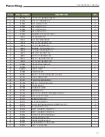
Page 31: ...PLE 1 2 BODY 1 2 14 NPTF QUICK CONNECT 2 9 812320 ADAPTER 8 MPT X 6 MJIC 2 10 812362 LOCK NUT 5 16 PL 2 11 81925 HEX BOLT 5 16 X 1 3 4 PL 1 12 886897 ADAPTOR STR 7 8MORB X 3 4MJIC S 2 13 913969 ELBOW 6 MPT X 6 FPT 90 1 14 914276 VALVE CHECK 8 MPT X 8 FPT 1 15 914818 BRKT HYD HOSE CLAMP 2 16 919398 ELBOW 6 FJIC X 6 MJIC 90 2 17 932238 HOSE 6 X 6 JIC X 6JIC L 54 2 18 932239 HOSE 4 X 6JIC X 6JIC L 73...

Page 32: ...Assembly Teleswing 30 ...

Page 33: ...Operation Teleswing 31 OPERATION GENERAL INFORMATION 33 Pre Operation Checklist 33 Break In Checklist 34 OPERATION 35 Functions 35 Order of Operations 36 Adjustments 37 ...

Page 34: ...Operation Teleswing 32 ...

Page 35: ...is or loose material is present Engine is running Tools are being used 1 Lubricate the equipment per the schedule outline in the Maintenance Section 2 Check the augers Remove any material build up or debris that has become entangled 3 Make sure that all guards and shields are in place secured and functioning as designed WARNING HIGH PRESSURE FLUID HAZARD Leaking fluids under pressure can enter the...

Page 36: ... Always keep PTO shields and all guards in place when using PTO driven equipment Disengage PTO for road travel Keep hands feet and clothing away Check the following mechanical items after 1 hour of operation and again after 10 hours of operation 1 Re torque wheel bolts to proper torque and check tire pressure 2 Check for loose fasteners and hardware Tighten as required 3 Check the condition of all...

Page 37: ...quipment and the operator The flow should be turned down to the point where the operator is comfortable with the swing speed and the retraction speed while holding onto the controls As with all swing augers It is possible for the swing to overfeed the main auger if the main auger is approaching or exceeding its maximum angle The auger capacity drops significantly with increased angle Whereas the a...

Page 38: ...ition auger over bin for unloading 2 Lower the Teleswing from transport and swing around to appropriate unloading position The Teleswing should be perpendicular to auger 3 Fully retract theTeleswing 4 Move the unloading unit into position Center the discharge chutes of the unloading unit 2 ft from the end of theTeleswing hopper 5 Lower the Teleswing hopper tip and extend hopper under unloading uni...

Page 39: ...to the top hole Item 1 on the mounts and reinstall hardware Figure 12 Adjusting hydraulic tilt cylinder Figure 13 Extend the rod end of the tilt hydraulic cylinder Item 1 by loosening the set screw on the yoke and unthreading the yoke from the rod Figure 13 Unthread the yoke three full rotations The amount to be unthreaded may vary It is possible to unthread the yoke too far which will cause the d...

Page 40: ...Operation Teleswing 38 ...

Page 41: ...NANCE TROUBLESHOOTING 41 Chart 41 SERVICE SCHEDULE 42 Maintenance Intervals 42 TIRE PRESSURE 43 LUBRICATION 43 Lubrication Locations 44 STORAGE AND RETURNTO SERVICE 45 Storage 45 ReturnTo Service 45 SAFETY SIGN DECAL INSTALLATION 45 ...

Page 42: ...Maintenance Teleswing 40 ...

Page 43: ...Farm King dealer Before you call please have this Operator And Parts Manual and the serial number of your machine at hand PROBLEM CAUSE CORRECTION Cannot start augers Plugged auger or obstruction Shutoff tractor and disconnect the PTO Remove obstruction Bearing failure Check bearings and replace if required Grain flow is too fast Discharge gate s open too far Close the gate s to allow a slower gra...

Page 44: ...n the manuals when making repairs adjustments or servicing Check for correct function after adjustments repairs or service Untrained operators and failure to follow instructions can cause injury or death Item DESCRIPTION SERVICE PROCEDURES Check Clean Lube Change Cover Daily Maintenance or every 8 hours 1 Bushing Hopper Feed Screw 2 Bushing Hopper Jack Shaft 3 Bushing Transition Screw Every 80 Hou...

Page 45: ...ease etc must be disposed of in an environmentally safe manner Some regulations require that certain spills and leaks on the ground must be cleaned in a specific manner See local state and federal regulations for the correct disposal TIRE PRESSURE CAUTION When inflating tires use a clip on chuck and extension hose long enough to allow you to stand to one side and NOT in front of or over the tire a...

Page 46: ...Maintenance Teleswing 44 Lubrication Locations Figure 14 12 12 9 3 5 13 13 1 1 4 2 10 11 10 6 6 ...

Page 47: ...if required ReturnTo Service After the equipment has been in storage it is necessary to follow a list of items to return the equipment to service Be sure all shields and guards are in place Lubricate the equipment Connect to a tractor and operate equipment verify all functions operate correctly Check for leaks Repair as needed SAFETY SIGN DECAL INSTALLATION IMPORTANT When replacing safety signs de...

Page 48: ...Maintenance Teleswing 46 ...

Page 49: ...3 MODELS 48 MAIN COMPONENTS 16 MODELS 52 COLLECTOR 13 MODELS 56 COLLECTOR 16 MODELS 60 ROLLER FLANGE 64 HYDRAULIC WINCH VALVE DRIVELINE 16 MODELS 66 WHEEL DRIVE 68 CHAINBOX 13 MODELS 70 CHAINBOX ANDTUBE 16 MODELS 72 HOPPER 13 MODELS 74 HOPPER 16 MODELS 78 HYDRAULICS 13 MODELS 82 HYDRAULICS 16 MODELS 84 ...

Page 50: ...ica Base ModelTeleswing Contact your Farm King dealer for additional parts information MAIN COMPONENTS 13 MODELS DETAIL A DETAIL B DETAIL C DETAIL D DETAIL E DETAIL F A B C D F E 38 46 39 10 1 34 31 40 14 18 43 3 18 2 15 27 32 53 55 50 22 2 15 30 2 15 35 28 29 11 20 6 4 6 49 47 26 56 33 24 44 41 42 13 12 25 23 16 37 8 34 9 48 52 7 5 21 5 45 51 17 54 932326 ...

Page 51: ...4 18 84050 3 4 S A E FLAT WASHER PL 4 19 84270 5 8 X 1 3 4 HEX BOLT PL 1 20 84299 5 8 X 2 HEX BOLT GR 5 PL 1 21 84498 1 4 LOCK NUT PL 4 22 86170 3 8 X 1 HEX BOLT GR 5 PL 2 23 86273 7 16 LOCK NUT PL 7 24 917706 CLAMP HOSE 15 375TO 17 375 2 25 930439 WELDT MAIN FLTG 1 26 930508 DOUBLE JOINT CAT 3 50 DEG 1 27 930847 WELDT RETRACTOR 1 28 931528 WEAR BUTTON 8 29 931529L PLATE SWIVEL SPACER BLOCK 4 30 9...

Page 52: ...odels Cont DETAIL A DETAIL B DETAIL C DETAIL D DETAIL E DETAIL F A B C D F E 38 46 39 10 1 34 31 40 14 18 43 3 18 2 15 27 32 53 55 50 22 2 15 30 2 15 35 28 29 11 20 6 4 6 49 47 26 56 33 24 44 41 42 13 12 25 23 16 37 8 34 9 48 52 7 5 21 5 45 51 17 54 932326 ...

Page 53: ...5 ENERGY CHAIN 12 FT 47 932304 COVER COLLECTOR PIVOT 1 48 932306 ENERGY CHAIN MOUNTING BRACKET 1 49 932309 SWIVEL RING SPACER BUSHING 2 50 932320 WELDT TRANSITION LID 1 51 932355 PLATE THREADED BACKING PLATE 2 52 932410 ENERGY CHAIN MOUNTING BRACKET 1 53 933153 U JOINT 1 1 4 X 1 1 4 1 54 934626 9 16 x 1 1 4 HEX BOLT GR 5 PL 4 55 960177 KEY 0 250 SQ 2 56 960180 U JOINT SPROCKET KEY 313 SQ X 1 375 1...

Page 54: ...ing 52 MAIN COMPONENTS 16 MODELS DETAIL C DETAIL B DETAIL A C 43 17 38 5 7 44 46 29 8 6 16 30 8 6 16 28 18 22 16 24 11 2 31 36 13 15 27 4 3 14 2 9 1 25 26 32 19 20 12 3 14 42 10 9 2 21 45 33 41 37 23 47 7 5 40 39 B A 34 35 933250 ...

Page 55: ...ECTOR COVER WEAR STRIP 4 19 931528 WEAR BUTTON 8 20 931529L PLATE SWIVEL SPACER BLOCK 4 21 931530 HOOD CATCH KIT 2 22 931640 1 4 X 1 FLAT SOCKET CAP SCREW GR 5 PL 12 23 931725 ASSY WHEEL DRIVE 1 24 932080 Q45 3 SPOOL HYDRAULIC VALVE 1 25 932117 10 24 X 3 4 PAN HEAD MACH SCREW GR 5 PL 4 26 932118 10 24 LOCK NUT PL 4 27 932242 HOPPER SWIVEL BUSHING 2 28 932295 ENERGY CHAIN 12 FT 29 932306 ENERGY CHA...

Page 56: ...4 MAIN COMPONENTS 16 MODELS CONTINUED DETAIL C DETAIL B DETAIL A C 43 17 38 5 7 44 46 29 8 6 16 30 8 6 16 28 18 22 16 24 11 2 31 36 13 15 27 4 3 14 2 9 1 25 26 32 19 20 12 3 14 42 10 9 2 21 45 33 41 37 23 47 7 5 40 39 B A 34 35 933250 ...

Page 57: ...RT NUMBER DESCRIPTION QTY 42 933165 5 16 18 UNC RIBBED RIVET NUT 6 43 933204 WELDT SWING RING 1 44 933205 SWING RING BUSHING 2 45 933208 WELDT WINCH MOUNT 1 46 934717 5 8 X 1 3 4 CARR BOLT GR 5 YZ PL 2 47 981664 5 8 X 2 1 4 HEX BOLT GR 5 PL 4 ...

Page 58: ...Teleswing 56 COLLECTOR 13 MODELS 36 13 15 51 46 45 47 31 32 17 7 38 22 6 20 14 4 55 54 8 49 19 4 26 35 1 15 5 2 9 3 37 16 4 28 34 43 27 39 24 56 40 44 25 52 46 45 47 21 5 48 33 18 42 29 9 10 11 50 30 41 23 4 12 4 53 931641 ...

Page 59: ...EX BOLT PL 1 18 84498 1 4 LOCK NUT PL 12 19 86170 3 8 X 1 HEX BOLT GR 5 PL 12 20 86171 3 8 X 1 1 4 HEX BOLT PL 2 21 87553 1 2 X 1 3 4 HEX BOLT PL 2 22 930980 PINION ROLLER SPACER 1 23 930982 COLLECTOR STOP 2 24 930985L PLATE DOOR 1 25 930986 PINION RIGHT SIDE SEAL 1 26 930989 TRACK ROLLER 1 27 930991 WELDT 16TOOTH SPROCKET AND HUB 1 28 930994 BRKT GEARBOX Z BRACKET 1 29 930997 WELDT COLLECTOR COVE...

Page 60: ...leswing 58 Collector 13 Models Cont 36 13 15 51 46 45 47 31 32 17 7 38 22 6 20 14 4 55 54 8 49 19 4 26 35 1 15 5 2 9 3 37 16 4 28 34 43 27 39 24 56 40 44 25 52 46 45 47 21 5 48 33 18 42 29 9 10 11 50 30 41 23 4 12 4 53 931641 ...

Page 61: ...10 24 X 3 4 PAN HEAD MACH SCREW GR 5 PL 14 47 932118 10 24 LOCK NUT PL 14 48 933133 WELDT RIGHT SWING RING MOUNT BRACE 1 49 933134 WELDT LEFT SWING RING MOUNT BRACE 1 50 933165 5 16 18 UNC RIBBED RIVET NUT 6 51 934237 PLATE CB RIGHT SIDE SEAL 1 52 934238 PINION LEFT SIDE SEAL 1 53 934701 ASSY ROLLER FLANGE 1 54 934732 1 4 X 1 1 2 SOCKET CAP SCREW FULLTHR GR 5 1 55 960789 WOODEN BEARING 1 3 8 1 56 ...

Page 62: ...Parts Identification Teleswing 60 COLLECTOR 16 MODELS 28 17 5 31 25 26 15 18 7 6 33 32 34 2 9 3 14 4 35 16 12 4 11 36 20 46 23 5 13 1 40 30 22 27 41 37 45 33 32 34 44 8 42 11 39 38 29 19 10 43 4 932941 ...

Page 63: ...HEX BOLT PL 2 18 930980 PINION ROLLER SPACER 1 19 930982 COLLECTOR STOP 2 20 930985L PLATE DOOR 1 21 930989 TRACK ROLLER 1 22 930991 WELDT 16TOOTH SPROCKET AND HUB 1 23 931005 PLATE WEAR STRIP 2 24 931427 TRACK ROLLER BEARING 2 25 931593 WELDT PINION SPROCKET 1 26 931594 PINION ROLLER 1 27 931596 DOUBLE 60 CHAIN 1 28 931597 BRAKE MOTOR 1 29 931616 3 8 X 2 1 4 SOCKET CAP SCREW GR 5 PL 2 30 931662 5...

Page 64: ...rts Identification Teleswing 62 Collector 16 Models Cont 28 17 5 31 25 26 15 18 7 6 33 32 34 2 9 3 14 4 35 16 12 4 11 36 20 46 23 5 13 1 40 30 22 27 41 37 45 33 32 34 44 8 42 11 39 38 29 19 10 43 4 932941 ...

Page 65: ...leswing 63 ITEM PART NUMBER DESCRIPTION QTY 42 932940 WELDT COLLECTOR 1 43 934701 ASSY ROLLER FLANGE 1 44 934732 1 4 x 1 1 2 SOCKET CAP SCREW FULLTHR GR 5 1 45 934757 UPPER COLLECTOR END SEAL LEFT 1 46 968601 5 16 WING NUT 5 ...

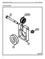
Page 66: ...Parts Identification Teleswing 64 ROLLER FLANGE 5 2 1 3 4 6 3 7 934701 ...

Page 67: ...EM PART NUMBER DESCRIPTION QTY 1 812364 1 2 LOCK NUT PL 1 2 81633 1 2 X 5 HEX BOLT PL 1 3 84048 1 2 SAE FLAT WASHER PL 3 4 930989 TRACK ROLLER 1 5 930990 PLATE ROLLER FLANGE 1 6 931427 TRACK ROLLER BEARING 2 7 931599 SPLINETUBE BEARING 1 ...

Page 68: ...Parts Identification Teleswing 66 HYDRAULIC WINCH VALVE DRIVELINE 16 MODELS DETAIL A DETAIL B A B 17 13 7 2 23 18 6 19 21 16 15 3 27 14 5 20 8 12 25 22 26 1 9 8 32 7 11 10 11 4 28 30 31 24 29 Y1621 ...

Page 69: ... PL 4 14 886897 ADAPTOR STR 7 8MORB X 3 4MJIC S 2 15 909935 ADAPTOR CHECK VALVE 8 MORB 8 MJIC 1 16 909936 ADAPTER 12MORB X 8FORB 1 17 910483 WARN HYDRAULIC WINCH 1 18 910490 HYD WINCH SHIELD 7GA 1 19 910508 WINCH CABLE ASSEMBLY 1 4 1 20 910523 1 4 X 2 3 4 HEX BOLT PL 3 21 912250 HOSE 1 2 X 138 1 2 MNPT X 3 4 SWFJIC 90 2 22 914640 HOSE CLAMP TWIN 0 787 DIA 1 23 914931 HOSE 8 X 8FJIC X 8FJIC 90 DEG ...

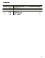
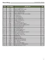
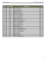
Page 70: ...Parts Identification Teleswing 68 WHEEL DRIVE 21 4 6 16 8 24 25 5 6 9 17 12 19 10 2 3 13 11 18 2 3 22 14 20 15 23 7 1 931725 ...

Page 71: ... 2 10 915665 WHEEL STUD NUT WB11 10 11 931697 WELDT INNER ROTATING HUB 1 12 931698 WELDT OUTER ROTATING HUB 1 13 931703L PLATE FRONT STIFFENER 1 14 931705L PLATE OUTER WASHER 2 15 931708 16X6 50 8 SUPER LUG 5 BOLT 2 16 931710 WHEEL DRIVE MOTOR 1 17 931712 WHEEL DRIVE BUSHING 4 18 931713 WELDT DRIVE SPROCKET HUB 1 19 931722 1 1 4 X 1 2 UNF WHEEL STUD GR 8 10 20 931723 WELDT TIGHTENER HUB 2 21 93172...

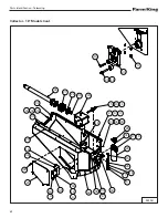
Page 72: ...Parts Identification Teleswing 70 CHAINBOX 13 MODELS 7 5 4 10 7 21 9 24 13 20 11 31 1 6 12 10 7 3 19 30 14 18 17 27 2 8 28 23 22 26 16 15 25 4 29 931584 ...

Page 73: ... BRACKET 1 14 930953 SPLINED SHAFT 1 15 930968L PLATE UPPER DRIVE SPACER 1 16 930969L PLATE UPPER WASHER CB 1 17 931428 1 2 X 2 5 CARRIAGE BOLT GR 5 YZ PL 1 18 931431 1 2 X 1 UNF HEX BOLT GR 8 YZ PL 1 19 931501 WELDT CHAINBOX 1 20 931505 IDLER SPROCKET 80 CHAIN 12TEETH 1 21 931507 WELDT 8020 SPROCKET AND HUB 1 22 931508 SPLINE SHAFT END BEARING HOUSING 1 23 931513 AUGER SHAFT BEARING HOUSING 1 24 ...

Page 74: ...Parts Identification Teleswing 72 CHAINBOX ANDTUBE 16 MODELS 23 19 39 40 41 1 8 25 22 29 35 17 3 26 33 32 30 20 10 2 14 27 9 11 6 24 7 9 5 16 21 15 18 34 28 4 11 9 31 DETAIL A A 36 37 38 933073 ...

Page 75: ...OLT GR 5 YZ PL 1 19 931431 1 2 X 1 UNF HEX BOLT GR 8 YZ PL 1 20 931505 IDLER SPROCKET 80 CHAIN 12TEETH 1 21 931513 AUGER SHAFT BEARING HOUSING 1 22 931514 WELDT 8020 SPROCKET AND SPLINE HUB 1 23 931515L PLATE HEAVY WASHER 1 24 931516 SPLINE SHAFT INNER BEARING HOUSING 1 25 931799 WELDT COVER REINFORCEMENT 1 26 932061 3 8 X 1 UNF HEX BOLT GR 8 YZ PL 1 27 932627 FLANGE BEARING W LOCK COLLAR 1 28 932...

Page 76: ...ation Teleswing 74 HOPPER 13 MODELS DETAIL A A 37 16 38 20 34 39 33 45 1 4 35 28 5 2 32 45 47 36 7 6 13 42 11 14 23 24 46 9 11 14 21 30 22 29 7 6 13 10 12 3 25 44 43 27 47 2 8 26 31 41 9 40 15 48 17 14 11 19 18 932029 ...

Page 77: ...L PLATE SKIRT RETAINER 2 20 931891 ASSY 21TOOTH IDLER 1 21 932011 WELDT RIGHT FEED SCREW 1 22 932012 WELDT LEFT FEED SCREW 1 23 932015 FEED SCREW BUSHING 2 24 932017 WELDT FEED SCREW BUSHING HANGER 2 25 932018 ASSY TRANSFER SCREW 1 26 932022 GUARD HOPPER MESH 1 27 932023 BRKT TRANSITION INSPECTION COVER 1 28 932024 BRKT INNER CARRIAGE PLATE 2 29 932028 HOPPER SKIRT 1 30 932033 WELDT HOPPER JACK SH...

Page 78: ...on Teleswing 76 Hopper 13 Models Cont 932029 DETAIL A A 37 16 38 20 34 39 33 45 1 4 35 28 5 2 32 45 47 36 7 6 13 42 11 14 23 24 46 9 11 14 21 30 22 29 7 6 13 10 12 3 25 44 43 27 47 2 8 26 31 41 9 40 15 48 17 14 11 19 18 ...

Page 79: ... DESCRIPTION QTY 42 932214 FLANGE BEARING W LOCK COLLAR 2 43 933153 U JOINT 1 1 4 X 1 1 4 1 44 960177 KEY 0 250 SQ 3 45 967141 5 16 X 1 4 SOCKET SET SCREW BR 4 46 967164 DRIVE IN GREASE ZERK 2 47 968601 5 16 WING NUT 3 48 SZ01125118 KEY SQ 1 4 X 1 19 1 ...

Page 80: ... Teleswing 78 HOPPER 16 MODELS 23 18 24 20 38 27 52 21 49 37 17 26 41 22 1 4 5 2 16 43 40 45 19 10 15 11 3 7 12 9 14 6 44 36 32 51 31 29 50 30 29 50 28 13 3 47 16 48 49 10 11 15 46 51 39 34 35 33 25 8 6 14 8 6 14 42 932673 ...

Page 81: ...ATE UPPER WASHER CB 1 19 931508 SPLINE SHAFT END BEARING HOUSING 1 20 931891 ASSY 21TOOTH IDLER 1 21 932042 DOUBLE 21TOOTH 60 DRIVE 1 22 932052 HANDTRUCKTIRE WHEEL ASSEMBLY ZIGZAG 2 23 932061 3 8 X 1 UNF HEX BOLT GR 8 YZ PL 1 24 932208 EXTERNAL RETAINING RING 1 25 932623 WELDT HOPPER CHAIN GUARD 1 26 932627 FLANGE BEARING W LOCK COLLAR 2 27 932628 21TOOTH 60 SPROCKET AND HUB 1 28 932629 ASSY TRANS...

Page 82: ...leswing 80 Hopper 16 Models Cont 23 18 24 20 38 27 52 21 49 37 17 26 41 22 1 4 5 2 16 43 40 45 19 10 15 11 3 7 12 9 14 6 44 36 32 51 31 29 50 30 29 50 28 13 3 47 16 48 49 10 11 15 46 51 39 34 35 33 25 8 6 14 8 6 14 42 932673 ...

Page 83: ...932672 0 375 X 0 375 X 1 00 KEY 1 44 932676L PLATE SKIRT RETAINER 2 45 932678 EXTERNAL RETAINING RING 1 46 932680 EXTERNAL RETAINING RING 2 47 932681 U JOINT 1 48 960704 SPROCKET KEY 3 8 SQ X 1 1 2 LG 1 49 967141 5 16 X 1 4 SOCKET SET SCREW BR 6 50 967164 DRIVE IN GREASE ZERK 2 51 968601 5 16 WING NUT 4 52 985639 03 8 X 1 2 SOCKET SET SCREW BR 2 ...

Page 84: ...S 13 MODELS DETAIL A DETAIL B DETAIL C TO TILT HYD CYL TO WHEEL DRIVE MOTOR TO RETRACTOR MOTOR DETAIL D A B D C 2 20 24 7 5 3 21 22 23 8 26 17 4 6 9 14 1 19 10 18 25 13 10 18 13 19 21 22 24 24 24 23 16 LIFT BOOM SAFETY CHAIN 28 27 15 12 11 F2401 ...

Page 85: ...62 5 16 LOCK NUT PL 2 11 81546 5 16 FLAT WASHER PL 3 12 81549 5 16 X 3 4 HEX BOLT PL 3 13 81925 HEX BOLT 5 16 X 1 3 4 PL 2 14 886897 ADAPTOR STR 7 8MORB X 3 4MJIC S 2 15 909277 MANUAL HOLDER 3 1 2 X 12 1 16 913969 ELBOW 6 MPT X 6 FPT 90 1 17 914276 VALVE CHECK 8 MPT X 8 FPT 1 18 915817 CLAMP TWIN 0 63 2 19 915821 COVER TWIN CLAMP 2 20 919398 ELBOW 6 FJIC X 6 MJIC 90 2 21 932238 HOSE 6 X 6 JIC X 6J...

Page 86: ...S 16 MODELS DETAIL A DETAIL B DETAIL C DETAIL D A B C D 24 21 25 22 22 20 8 24 2 3 5 16 7 24 10 9 4 26 17 22 25 14 21 13 11 23 1 18 19 11 1 18 19 TO TILT HYD CYL TO WHEEL DRIVE MOTOR TO RETRACTOR MOTOR LIFT BOOM SAFETY CHAIN 28 27 15 12 6 F2448 ...

Page 87: ... ADAPTER 8 MPT X 6 MJIC 2 11 812362 5 16 LOCK NUT PL 2 12 81546 5 16 FLAT WASHER PL 3 13 81925 HEX BOLT 5 16 X 1 3 4 PL 1 14 886897 ADAPTOR STR 7 8MORB X 3 4MJIC S 2 15 909277 MANUAL HOLDER 3 1 2 X 12 1 16 913969 ELBOW 6 MPT X 6 FPT 90 1 17 914276 VALVE CHECK 8 MPT X 8 FPT 1 18 915817 CLAMP TWIN 0 63 2 19 915821 COVER TWIN CLAMP 2 20 919398 ELBOW 6 FJIC X 6 MJIC 90 2 21 932238 HOSE 6 X 6 JIC X 6JI...

Page 88: ...Parts Identification Teleswing 86 ...

Page 89: ...PPING KIT AND BUNDLE NUMBERS 89 HYDRAULIC CONNECTION SPECIFICATIONS 90 O Ring Fitting StraightThread 90 O Ring Face Seal Connection 90 Flare Fitting 90 Port Seal O Ring Boss Fitting 90 Tubelines And Hoses 90 HARDWARETORQUE VALUES 91 Metric Chart 91 Imperial Chart 92 ...

Page 90: ...Specifications Teleswing 88 ...

Page 91: ...Approx 11 000 bu hr Hopper 52 x 45 x 9 1 4 Model 16 Teleswing INFORMATION UNAVAILABLE SHIPPING KIT AND BUNDLE NUMBERS The following is a list of Kit Numbers for this product and the Bundle Numbers Descriptions and Quantities for each Kit Qty Bundle Description 13 Teleswing Telescopic Retracting Swing Auger 1 F2401 Base unit hydraulic winch not included 16 Teleswing Telescopic Retracting Swing Auge...

Page 92: ...e nut makes contact with the seat Use the chart Figure 57 to find the correct tightness needed Port Seal O Ring Boss Fitting Port Seal And O ring BossTighteningTorque Tubeline O D Thread Size N m ft lb 1 4 7 16 20 13 18 3 8 9 16 18 22 30 1 2 3 4 1 6 40 54 5 8 7 8 14 60 81 3 4 1 1 16 12 84 114 7 8 1 3 16 12 98 133 1 1 5 16 12 118 160 1 1 8 1 7 16 12 154 209 1 1 4 1 5 8 12 163 221 Note Port seal and...

Page 93: ...d Plated W ZnCr CL 8 W CL 8 8 Bolt M4 1 7 15 2 2 19 2 6 23 3 4 30 3 7 33 4 8 42 1 8 16 M6 5 8 51 7 6 67 8 9 79 12 102 13 115 17 150 6 3 56 M8 14 124 18 159 22 195 28 248 31 274 40 354 15 133 M10 28 21 36 27 43 32 56 41 61 45 79 58 30 22 M12 49 36 63 46 75 55 97 72 107 79 138 102 53 39 M16 121 89 158 117 186 137 240 177 266 196 344 254 131 97 M20 237 175 307 226 375 277 485 358 519 383 671 495 265 ...

Page 94: ... 35 26 46 34 50 37 65 48 26 19 35 26 7 16 37 27 47 35 57 42 73 54 80 59 104 77 41 30 57 42 1 2 57 42 73 54 87 64 113 83 123 91 159 117 61 45 88 64 9 16 81 60 104 77 125 92 163 120 176 130 229 169 88 65 125 92 5 8 112 83 145 107 174 128 224 165 244 180 316 233 122 90 172 127 3 4 198 146 256 189 306 226 397 293 432 319 560 413 217 160 306 226 7 8 193 142 248 183 495 365 641 473 698 515 904 667 350 2...

Page 95: ...Warranty Teleswing 93 WARRANTY FARM KING BASE LIMITED WARRANTY 95 Repair Parts Limited Warranty 95 What Is Not Covered 95 Authorized Dealer And Labor Costs 95 Warranty Requirements 96 ...

Page 96: ...Warranty Teleswing 94 ...

Page 97: ... serviced as provided for in the Operator s Manual to be free from defects in materials or workmanship for a period of thirty 30 days from the invoice date for the parts Farm King will fulfill this limited warranty by at its option repairing or replacing any covered part that is defective or is the result of improper workmanship provided that the part is returned to Farm King within thirty 30 days...

Page 98: ...T LIMITATION LOSS OF CROPS LOSS OF PROFITS OR REVENUE OTHER COMMERCIAL LOSSES INCONVENIENCE OR COST OF REPLACEMENT OF RENTAL EQUIPMENT IN NO EVENT SHALL FARM KING S CONTRACT OR WARRANTY LIABILITY EXCEED THE PURCHASE PRICE OF THE PRODUCT Note that some states do not allow limitations on how long an implied warranty lasts or the exclusion or limitation of incidental or consequential damages so the a...

Page 99: ......

Page 100: ...f Buhler Industries Inc 301 Mountain Street South Morden MB R6M 1X7 Toll Free 888 524 1004 E mail info buhler com www farm king com Equipment shown is subject to change without notice 2018 BuhlerTrading Inc Printed in CanadaTSX BUI ...

Reviews: