


10
tion, their overload protective switches should be con-
nected in series and then connected into the dryer
safety circuit. For recommended connections, refer to
motor overload protection connections shown in the
SAFETY CIRCUIT portion of the control circuit wiring
diagram in Section 8.
Voltage
1
r
230V
3
r
230V
3
r
460V
1
r
230V
3
r
230V
3
r
460V
1
r
230V
3
r
230V
3
r
460V
1
r
230V
3
r
230V
3
r
460V
1
r
230V
3
r
230V
3
r
460V
Top
Auger
5
5
5
22
13
6.5
C22.8
C16.3
C8.67
80
60
30
Btm.
Auger
3
3
3
16
8.6
4.3
C15.1
C11.3
C5.92
80
60
30
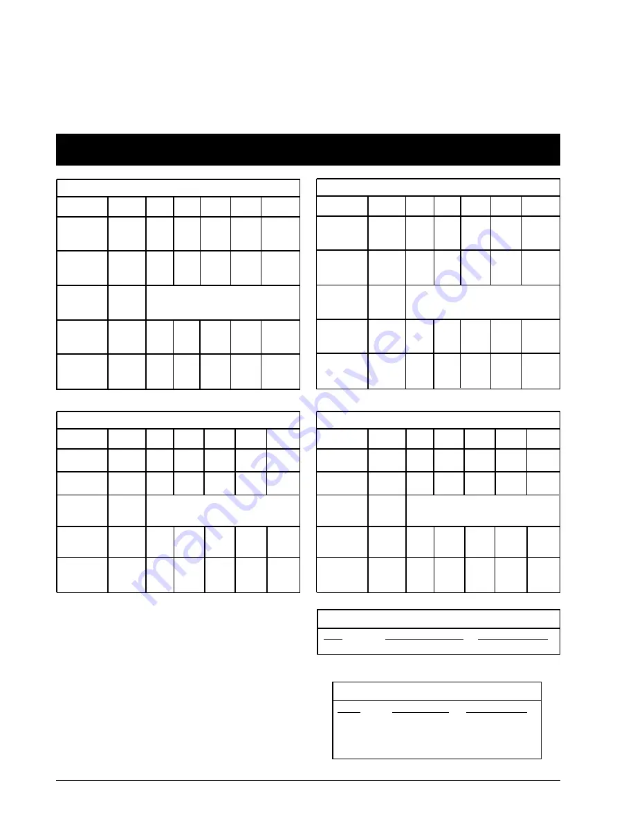
T A B L E 2 - 2 E L E C T R I C A L L O A D , O V E R L O A D
R E L A Y S , a n d C I R C U I T B R E A K E R S
C - 2 1 2 0 A
Top
Fan
10/13
10/13
10/13
58
36
18
F65.5
C36.6
C21.4
100
90
50
Btm.
Fan
7.5/9
7.5/9
7.5/9
42
28
14
F43.0
C30.3
C16.3
80
60
30
Aux.
Conv.
1
7.5 (two)
7.5 (two)
7.5 (two)
34
20
10
C30.3
C22.8
C13.7
--
2
--
2
--
2
145
86
43
Voltage
3
r
230V
3
r
460V
3
r
230V
3
r
460V
3
r
230V
3
r
460V
3
r
230V
3
r
460V
3
r
230V
3
r
460V
Top
Auger
7.5
7.5
20
10
C22.8
C13.7
90
50
Btm.
Auger
5
5
13
6.5
C16.3
C8.67
90
50
C - 2 1 3 0 A
Top
Fan
20
20
56
28
E77
C33.0
100
50
Btm.
Fan
13
13
36
18
C36.6
C21.4
60
50
Aux.
Conv.
1
10 (two)
10 (two)
26
13
C30.3
C16.3
--
2
--
2
132
66
Horsepower
Full Load
Amps
Max Running
Load (dryer
only, amps)
Circuit
Breaker
Rating -
amps
Overload
Heater
Element
Voltage
3
r
230V
3
r
460V
3
r
230V
3
r
460V
3
r
230V
3
r
460V
3
r
230V
3
r
460V
3
r
230V
3
r
460V
Top
Auger
10
10
26
13
C30.3
C16.3
90
50
Btm.
Auger
7.5
7.5
20
10
C22.8
C13.7
90
50
C - 2 1 4 0 A
Top
Fan
25
30
66
33
E78
E72
100
63
Btm.
Fan
13
13
34
17
C36.6
C21.4
60
50
Aux.
Conv.
1
10 (two)
10 (two)
26
13
C30.3
C16.3
--
2
--
2
154
77
Horsepower
Full Load
Amps
Max Running
Load (dryer
only, amps)
Circuit
Breaker
Rating -
amps
Overload
Heater
Element
Voltage
1
r
230V
3
r
230V
3
r
460V
1
r
230V
3
r
230V
3
r
460V
1
r
230V
3
r
230V
3
r
460V
1
r
230V
3
r
230V
3
r
460V
1
r
230V
3
r
230V
3
r
460V
Top
Auger
5
5
5
22
13
6.5
C22.8
C16.3
C8.67
80
60
30
Btm.
Auger
3
3
3
16
8.6
4.3
C15.1
C11.3
C5.92
80
60
30
C - 2 1 2 5 A
Top
Fan
10/16
10/16
10/16
83
41
20.5
F84.8
C44
C25
100
90
50
Btm.
Fan
10
10
10
58
25
12.5
F65.8
C33.0
C18.0
80
60
30
Aux.
Conv.
1
7.5 (two)
7.5 (two)
7.5 (two)
34
20
10
C30.3
C22.8
C13.7
--
2
--
2
--
2
186
96
51
Horsepower
Full Load
Amps
Max Running
Load (dryer
only, amps)
Circuit
Breaker
Rating -
amps
Overload
Heater
Element
Horsepower
Full Load
Amps
Max Running
Load (dryer
only, amps)
Circuit
Breaker
Rating -
amps
Overload
Heater
Element
NOTES:
1. The motor current and maximum dryer running loads listed
above are based on auxiliary conveyor motor sizes shown.
The maximum size motor that can be powered directly through
the dryer’s ASC control is listed in the Aux. Motor Data chart.
All larger than maximum auxiliary conveyor motors require
separate contactors and overload protectors with coil circuits
connected to the dryer for automatic operation.
IMPORTANT:
All standard Model C-2100A dryers are factory
equipped with overload relay heater elements sized for auxil-
iary motors listed in charts above. If the actual auxiliary motors
used are of a different size, the elements must be changed.
2. Auxiliary motors are controlled by the top and bottom auger cir-
cuit breakers.
Size
3/4 HP DC
SCR MOTOR DATA
Control Amps / Volts
7.5A / 230VAC
Motor Amps / Volts
4.8A / 155VDC
Model
C-2120A
C-2125A
C-2130A
C-2140A
AUXILIARY MOTOR DATA
Std. Aux. Motor
7.5 HP
7.5 HP
10 HP
10 HP
Max. Aux. Motor
10 HP (
3
r
230V)
10 HP (
3
r
230V)
15 HP (
3
r
230V)
15 HP (
3
r
230V)
Summary of Contents for C-2120A
Page 8: ...6 ...
Page 18: ...16 ...
Page 22: ...20 ...
Page 34: ...32 ...
Page 38: ...Fig 6 8 ASC control panel internal view 36 Fig 6 7 ASC control panel ...
Page 39: ...37 Fig 6 9 C 2100A power panel typical 3 phase model shown ...
Page 44: ...42 ...
Page 53: ...51 Fig 8 1 C 2100A power circuit 220V 1 phase ...
Page 54: ...52 Fig 8 2 C 2100A power circuit 220V 3 phase models ...
Page 55: ...53 Fig 8 3 C 2100A power circuit 440V 3 phase models ...
Page 56: ...54 Fig 8 4 C 2100A general control circuit p 1 of 3 ...
Page 57: ...55 Fig 8 4 C 2100A general control circuit p 2 of 3 ...
Page 58: ...56 Fig 8 4 C 2100A general control circuit p 3 of 3 ...
Page 59: ...57 Fig 8 5 C 2100A burner control circuit circuit ...
Page 60: ...58 ...
Page 66: ...64 ...
Page 67: ......