13400 Owner’s Manual
P/N 446613 Issue I Rev. A
I-3
from the front of the control unit and displays system status LED’s and the four initiating
device circuits. Push buttons are used for operator interaction and are accessed by
opening the door.
Transformer Assembly
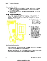
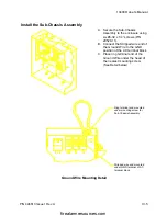
The Transformer Assembly plugs into the Main Board and is mounted on the side of the
chassis which mounts in the backbox. The Transformer Assembly comes in a 120 VAC
or a 240 VAC version.
Enclosure
The enclosure is manufactured of painted sheet steel and is sized to fit between 16”
O.C. wall studs and to be recessable in a semi-flush installation. Because of the need
to segregate high voltage and nonpower-limited circuits from power-limited circuits,
there are a limited number of acceptable conduit entry points. Combination 1/2 or 3/4
inch conduit knockouts are provided in the top and bottom of the backbox. The door
assembly mounts with slip hinges and locks for service access. A 12 Amp Hour battery
set may mounted in the bottom of the enclosure. Batteries larger than 12 AH require an
external UL listed battery cabinet.
Optional Control Unit Configuration
Operation of the base 13400 control unit is expandable as follows.
Alarm Relay Board (P/N 13402)
The Alarm Relay Board provides 1 system alarm, 1 system trouble and 4 zone alarm
relays with form “C” contacts, rated for 2 amps at 30 VDC and .5 amps at 30 VAC.
The board mounts to the Main Board of the 13400 Fire Alarm System Control Unit.
City Tie Board (P/N 13403)
The City Tie Board provides a supervised output for local energy municipal box
transmitter and alarm and trouble reverse polarity circuits. There is also a disable switch
and a trouble LED. The alarm reverse polarity output can be configured to open on
trouble if no alarm exists. The board mounts to the Main Board of the 13400 Fire Alarm
System Control Unit.
Remote LED Annunciator Driver Board (P/N 13406)
The 13400 control unit provides an optional drive for a remote annunciator. While the
remote interface is via individual drive circuits, the physical connection between the
control unit and the annunciator uses parallel data and draws all power from the control
unit. The control unit will supervise 1 remote unit. Annunciator wiring is supervised for
open conditions.. The board mounts to the Main Board of the 13400 Fire Alarm System
Control Unit.
Optional Devices
firealarmresources.com


