background image

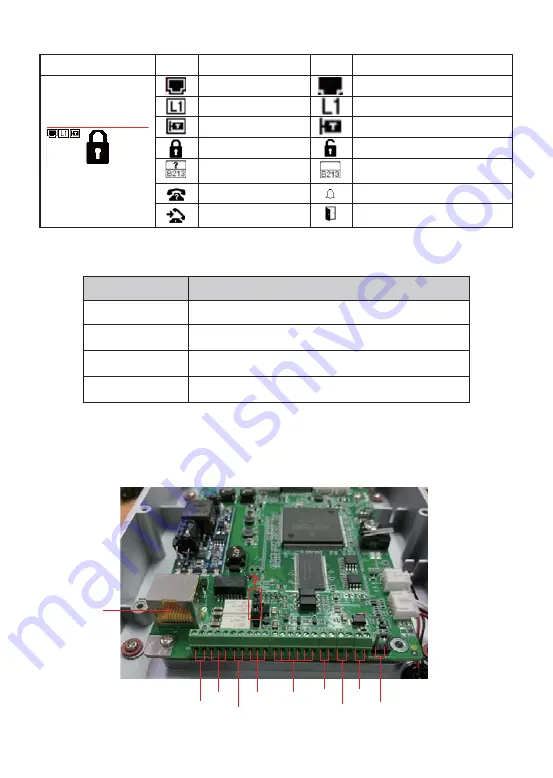
2) Interface description

LCD

Status

Description

Status

Description

Connected to the Internet

SIP register success 

Connected to the TR069

Lock off

Fault prompt 1 (with error 
number)

Call failed (no response)

Dialing

Not connected to the Internet, flashing

SIP register fail, flashing

Not connected to the TR069, flashing

Lock on

Fault prompt 12 


?: flashing)

Ringing

Open the door

LCD

Function Key

Call Key, Enter the number and press C to dialing out.

C

K

Key

Description

Password mode,“K password # ”

B

Numeric keypad

Backspace Key, Enter the number and press B to delete

Input password or dialing

        Open the rear case of the device, there is a row of terminal blocks for connecting 
the power supply, electric lock control, etc. The connection is as follows:

ʒ

ʓ

ʔ

ʕ

ʖ

ʗ

ʘ

ʙ

ʚ

ʛ

Summary of Contents for i33V

Page 1: ...www fanvil com 7JEFP PPS 1IPOF 2VJDL OTUBMMBUJPO VJEF i33V i33VF ...

Page 2: ... Speaker Camera Numeric keypad password and dialing RFID area RFID Card Screw and Wrench Photoresistor LCD Function key Package Contents www fanvil com i33V i33VF 7JEFP PPS 1IPOF 2VJDL OTUBMMBUJPO VJEF Mounting dimensions Unit MM Physical specification MIC Mounting dimensions Mounting dimensions Unit MM i33V i33VF ...

Page 3: ...g Not connected to the TR069 flashing Lock on Fault prompt 12 flashing Ringing Open the door LCD Function Key Call Key Enter the number and press C to dialing out C K Key Description Password mode K password B Numeric keypad Backspace Key Enter the number and press B to delete Input password or dialing Open the rear case of the device there is a row of terminal blocks for connecting the power supp...

Page 4: ...ectric lock alarm device etc Wiegand interface Two sets of door magnetic detection Temperature control power interface 12V 1A input Power interface 12V 1A input JP1 jumper ծ JP1 Jumper There are two modes for power supply of electric lock as shown in the picture below The default is Passive Mode Passive Mode When the electric lock starting current is more than 12V 500mA need to use the external dr...

Page 5: ...ring instructions Driving Mode Electric lock Mode Active Passive No electricity when open Electrify when open ɭ ɭ ɭ ɭ ɭ ɭ JP1 Jumper Connections NO Normally Open Contact COM Common Contact NC Normally Close Contact ...

Page 6: ...hat may be required Ӫ Hex wrench Ӫ Phillips screwdriver hammer RJ45 crimper Ӫ Electric impact drill with an 8mm drill bit Step 2 Drilling Figure 3 3 Wall Mounting Built in A Place the mounting template with dimensions on the surface of a wall in a desired flat position B Use an electric drill to drill the 4 holes marked on the mounting template It is recommended to drill about 50mm deep Remove the...

Page 7: ...e 6 screws on the back of the rear case and separate the rear case as shown in Figure 3 6 Figure 3 6 Step 4 Install the wall bracket wiring and casing A Align the screw holes of the wall bracket with the holes in the wall and fix them to the wall with the TA5 x40mm screws as shown in Figure 3 7 B Pass all the wires through the silicone plug in the middle of the bottom case All lines should be rese...

Page 8: ... Pass all the wires through the silicone plug in the middle of the bottom case All lines should be reserved for 15 20CM length as shown in Figure 3 8 Note The outlet hole of the bottom case faces down B Connect the cables of RJ45 power and electric lock to the motherboard socket as mentioned in connectors description refer to Section 2 C Connect the terminal of the wired cable to the motherboard s...

Page 9: ...word are both admin Step 2 Add the SIP account Set SIP server address port user name password and SIP user with assigned SIP account parameters Select Activate and then click Apply to save this setting In addition device provides the device surface DSS key operation to switch IP address acquisition mode Long press the DSS key for 10 seconds to be issued by the speaker Beep and then press the DSS k...

Page 10: ...89 Step 2 Use the device s Numeric Keyboard to input password and key and then the door will be unlocked 2 Private Access Code Step 1 Go to 6 FFHVV ĺ FFHVV 5XOH ĺ VHW Access Code Step 2 Use the device s Numeric Keyboard to press K and enter the Access Code and press to end the door will be unlocked Door Unlocking Setting ...

Page 11: ...to Access Table Step 2 Use pre assigned RFID cards to unlock the door by touching RFID area of device Remote Password Step 1 Go to 6 6HWWLQJ ĺ HDWXUHV ĺ 6HW Remote Password The default is Step 2 To answer the call made by visitor via SIP phone press the key to unlock the door the visitor ...

Page 12: ...Fanvil Technology Co Ltd Email sales fanvil com Tel 0755 2640 2199 Add 4F Block A Building 1 GaoXinQi Hi Tech Park Phase II 67th District Bao An Shenzhen China Fax 0755 2640 2618 P C 518101 ...

Reviews: