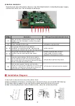
2) Interface description
①
②
③
④ ⑤ ⑥
⑦ ⑧
Serial
number
Description
Wiring port description(example above)
①
Ethernet interface: standard RJ45 interface, 10/100M
adaptive, it is recommended to use five or five types of
network cable
Two groups of short-circuit input detection
interfaces: for connecting switches, infrared probes,
door magnets, vibration sensors and other input devices
Left positive, right grounded
Two groups of short-circuit output control
interface: used to control electric locks, alarms,
etc.
Left grounded, right recording output
Recording output interface: Mix the device and the
sound of the far-end call. One is the recording signal
line, and the other is the ground line (be sure to ground
the line, otherwise there will be noise)
Left grounded, right external active speaker
②
③、⑤
④、⑥
⑦
⑧
2
Power interface: 12V/1A input
Left IN, right OUT
Left (NC): Normally Close Contact
Center (COM): Common Contact
Right (NO): Normally Open Contact
External active speaker interface: external active
speakers for audio power amplification. One is the audio
signal line, and the other is the ground line (be sure to
ground the line, otherwise there will be noise)
Open the rear case of the device, there is a row of terminal blocks for connecting the power supply,
electric lock control, etc. The connection is as follows:
1) Use built-in screw tool to remove the surface shell;
2) Based installation dimensions, mounting hole in the wall to draw, use an electric drill holes lay;
3) The white rubber plugged into the wall and the bottom fixed with screws to the wall;
4) After connecting the power cord and network cable, screw the surface shell fixed.
Installation Diagram
3


