Fantek T-116 Operating Instructions Manual Download Page 23

2.17.- Ground connection device, ACC/29. 

2.18.-  Wheels  for  transporting  the  tower  in  upright  or  folded  position  to  its  working 

location. 

3. Safety precautions

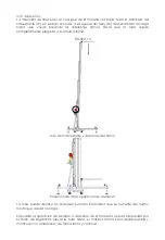
3.1.- Place the tower only on a solid and flat surface. 

3.2.- Check that the legs are fully inserted and secured by the retaining safety triggers 

(R). 

3.3.-  With  the  bubble  level  (F)  located  at  the  base  profile,  check  that  the  tower  is  in 

vertical  position.  If  necessary,  adjust  its  alignment  with  the  plates  (Q)  by  turning  the 

handle (H) in the appropriate sense, always keeping the base wheels in touch with the 

ground as another supporting point. 

3.4.- When used out in the open, place the tower on hard ground and secure it against 

wind  force  by  means  of  steel  cable  braces.  These  steel  cable  braces  must  have  a 

minimum diametre of 6 mm. 

3.5.-  If  necessary,  the  tower  must  be  anchored  to  the  ground  with  the  appropriate 

connecting device ACC/29. 

3.6.- Do not use ladders on the tower nor lean them on it. 

3.7.- Be careful with any cables, prominent objects etc. placed above the tower. 

3.8.- Do not stand under the load. 

3.9.- Do not move the tower when it is elevated with a load. 

3.10.- Before using the tower, check the state of the cable. This must be free of cuts and 

fraying. Never use cables in bad condition. 

3.11.-  Never  dismount  the  winch  handle  (W)  or  any  element  of  the  winch  under  any 

circumstances. 

3.12.-  Once  the  tower  is  ready  in  its  working  position  it  is  recommended  to  lock  the 

winch handle. 

3.13.- The minimum load for a safe operation of the brake is 25 kg. The brake will not 

function without this minimum load. 

3.14.- Do not grease or lubricate the brake mechanism of the winch. 

3.15.- Not permitted for use as passenger lift. 

3.16.-  For  transportation  it  is  necessary  to  retract  all  profiles  and  lock  them  with  the 

brake (O). 

4. Operation

4.1.- Place the tower on a flat and solid surface in its site of operation. 

Summary of Contents for T-116

Page 1: ...E ELEVATOR TOWER OPERATING INSTRUCTIONS GB TRAVERSENLIFT BEDIENUNGSANLEITUNG D T 116 T 116 TORRE ELEVADORA MANUAL DE INSTRUCCIONES E ELEVATOR TOWER OPERATING INSTRUCTIONS GB TRAVERSENLIFT BEDIENUNGSAN...

Page 2: ...fantekFerros y Aluminio Navarro S L...

Page 3: ...N1 N2 W S R F V J U O L T Q H P N1 N2 W N1 N2 W S R F V J U O L T Q H P Q H P fantekFerros y Aluminio Navarro S L...

Page 4: ...A B T 116 016 A B T 116 016 fantekFerros y Aluminio Navarro S L...

Page 5: ...26 T 116 002 T 116 026 ACC 26 T 116 020 T 116 015 T 116 020 T 116 026 B B1 T 116 029 T 116 003 A ACC 26 T 116 002 T 116 026 ACC 26 T 116 020 T 116 015 T 116 015 T 116 020 T 116 026 B B1 T 116 029 T 11...

Page 6: ...16 T 116 001 ACC 29 C T 116 009 T 116 010 T 116 011 T 116 006 ACC 28 T 116 005 T 116 007 ACC 13 ACC 21 ACC 19 T 116 014 T 116 013 T 116 012 T 116 016 T 116 001 ACC 29 T 116 011 T 116 006 ACC 28 T 116...

Page 7: ...16 025 T 116 004 EN FUNCIONAMIENTO T 116 026 T 116 026 T 116 021 T 116 022 ACC 26 T 116 027 B1 T 116 021 T 116 025 T 116 004 EN FUNCIONAMIENTO T 116 026 T 116 026 T 116 021 T 116 022 ACC 26 ACC 26 T 1...

Page 8: ...CC 16 001 ACC 16 003 ACC 16 004 ACC 16 003 T 116 024 ACC 14 002 ACC 14 001 ACC 14 ACC 12 002 C ACC 14 003 ACC 16 002 ACC 16 004 ACC 16 ACC 16 002 ACC 16 001 ACC 16 003 ACC 16 004 ACC 16 003 ACC 16 002...

Page 9: ...BLOQUEADO T 116 004 T 116 017 ACC 28 T 116 025 ACC 23 ACC 19 T 116 018 T 116 019 BLOQUEADO T 116 004 T 116 017 T 116 017 ACC 28 ACC 28 T 116 025 ACC 23 ACC 19 ACC 19 T 116 018 T 116 018 T 116 019...

Page 10: ...levable de 150 Kg 2 2 Carga m nima elevable de 25 Kg 2 3 Altura m xima 5 50 m 2 4 Altura m nima 1 70 m Altura de carga 0 20 m 2 5 rea de la base 1 70 x 1 60 m 2 6 rea de la base cerrada 0 42 x 0 42 m...

Page 11: ...o y acabado por anodizado tambi n en color negro 2 17 Dispositivo de conexi n de toma a tierra ACC 29 2 18 Ruedas direccionales para el transporte de la torre en posici n vertical y plegada hasta su e...

Page 12: ...trav s del dispositivo de conexi n habilitado para ello ACC 29 3 6 No usar escaleras encima de la torre ni apoyarlas en ella 3 7 Cuidado con salientes cables etc Por encima de la torre 3 8 No ponerse...

Page 13: ...e la parte frontal y las patas cortas sobre la parte trasera FIGURA 1 Introducir las Patas Comprobar los Gatillos de Seguridad 4 3 Ajustar la posici n vertical de la torre mediante los platillos de ap...

Page 14: ...tar los pasadores L Sacar las horquillas de carga U 3 3 3 3 4 4 4 4 Posicionar las horquillas en posici n Colocar los pasadores de seguridad La posici n de las horquillas de carga U en posici n de car...

Page 15: ...de 25 cm desde la parte trasera de las horquillas de carga FIGURA 5 25 cm Carga M xima 25 cm Carga M xima Posici n de la carga 4 6 En los montajes que se utilicen varias torres de carga frontal T 107...

Page 16: ...ovidas por el viento u otra fuerza externa incrementando la necesaria resistencia debido a la aplicaci n de fuerzas din micas sobre la torre FIGURA 7 4 8 Elevaci n Quitar el freno O y elevar la torre...

Page 17: ...del freno autom tico accionado por la carga FIGURA 9 Posici n de la torre elevada La torre puede dejarse en cualquier posici n intermedia que se necesite soltando simplemente la manivela Se recomiend...

Page 18: ...IGURA 10 Giro del cabrestante y descenso del tramo Posici n final de la operaci n de descenso La torre puede dejarse en cualquier posici n intermedia que se necesite del mismo modo que al subir la car...

Page 19: ...ontar las patas liberando los gatillos de retenci n y colocarlas en su posici n de transporte S Apretar los tornillos de sujeci n J FIGURA 11 Posici n de Transporte Es muy importante accionar el freno...

Page 20: ...cos de freno han sido engrasados con una grasa especial resistente al calor y la presi n No deben ser utilizados otros productos distintos al original suministrado por la empresa para evitar influir n...

Page 21: ...ron T 116 022 Juego tornillo polea nylon Acero Zincado T 116 023 Tope interior Tornillo Juego Zamak Zamak T 116 024 Tap n pl stico pata Pl stico Negro T 116 025 Cu a Tornillo Pl stico Blanco T 116 026...

Page 22: ...eights 2 1 Max load 150 kg 2 2 Min load 25 kg 2 3 Max height 5 50 m 2 4 Min height 1 70 m Min height for the load 0 20 m 2 5 Base area 1 70 x 1 60 m 2 6 Folded base area 0 42 x 0 42 m 2 7 Weight 85 kg...

Page 23: ...d to the ground with the appropriate connecting device ACC 29 3 6 Do not use ladders on the tower nor lean them on it 3 7 Be careful with any cables prominent objects etc placed above the tower 3 8 Do...

Page 24: ...y means of a suitable support so that the load can only move in a vertical sense The minimum load must be at least 25 kg The maximum recommended load must never be placed farther than 25 cm from the f...

Page 25: ...oing to be transported to avoid slipping of the profiles 5 Maintenance 5 1 All cables must be checked regularly Faulty cables need to be replaced immediately Do not use the lifting tower with faulty c...

Page 26: ...5 5 In case a spare part is required it is necessary to indicate its reference number which can be found in the spare parts table in this manual SEE TABLE 1...

Page 27: ...htung auf unterschiedliche Nutzh he anzuheben 2 1 Maximallast 150 kg 2 2 Mindestlast 25 kg 2 3 Max H he 5 50 m 2 4 Min H he 1 70 m Min Lasth he 0 20 m 2 5 Stellfl che 1 70 x 1 60 m 2 6 Stellfl che zus...

Page 28: ...Falls notwendig den Lift mit dem hierf r vorgesehenen Verbindungselement ACC 29 am Boden verankern 3 6 Auf dem Lift keine Leitern verwenden und auch nicht daran anlehnen 3 7 Auf ber dem Lift h ngende...

Page 29: ...den Abbildung gezeigt ist SIEHE ABBILDUNG 4 4 5 Die anzuhebende Last mittels einer geeigneten Haltevorrichtung so auf den Lasttr gern des Lifts platzieren dass sie sich nur in vertikaler Richtung bewe...

Page 30: ...Transport des Lifts m ssen die Profile vollst ndig zusammengeschoben werden Den Rollwagen mit der Bremse O fixieren Die Beine nach Abziehen der Sicherungstrigger abnehmen und in ihre Transportpositio...

Page 31: ...herheit zu gew hrleisten d rfen nur Original Ersatzteile verwendet werden Der Betreiber verliert s mtliche Garantieanspr che sobald er andere als Original Ersatzteile einbaut oder irgendwelche Ver nde...

Page 32: ......

Page 33: ...tenidos en cuenta tanto en su totalidad como parcialmente los aspectos recogidos en las normas armonizadas siguientes UNE EN ISO 12100 1 2004 Seguridad de las m quinas Conceptos b sicos principios ge...

Page 34: ...ndard design Machinery Directive 98 37 EEC and that in its design and fabrication the following harmonized norms were taken into account EN ISO 12100 1 2004 Safety of machinery Basic concepts general...

Page 35: ...inenrichtlinie 98 37 EEC und dass bei seiner Konzeption und Herstellung die folgenden harmonisierten Normen ber cksichtigt wurden EN ISO 12100 1 2004 Sicherheit von Maschinen Grundbegriffe allgemeine...

Page 36: ...los cuatro a os Four years test UVV Pr fung alle 4 Jahre Fecha Date Datum Testado por Tested by Pr fer Notas Notes Anmerkung Firma Signature Unterschrift Examen anual a partir del cuarto a o Annual t...

Page 37: ...ft Fecha Date Datum Testado por Tested by Pr fer Notas Notes Anmerkung Firma Signature Unterschrift Fecha Date Datum Testado por Tested by Pr fer Notas Notes Anmerkung Firma Signature Unterschrift Fec...

Page 38: ...untries with specific regulations in this respect applicable by domestic rules or laws As a manufacturer we highly recommend to pass all the tests to prevent any damage and to ensure a perfect operati...

Page 39: ......

Page 40: ...Cam del Port 3 Pol Ind El Boni 46470 Catarroja Valencia Spain Tel 34 96 126 01 68 Fax 34 96 126 64 56 www fantek net e mail info fantek net...

Reviews: