background image

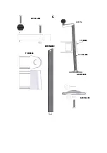
2.17.- Ground connection device, ACC/29. 

 
2.18.-Wheels for transport of the tower in vertical position and folded until its location of 

work.


3.- Safety precautions. 


3.1.- Placing the tower only upon hard and flat surfaces. 
 

3.2.- Check that the legs are inserted in depth and secure by the retaining security 

triggers (R). 
 

3.3.- Check that the tower is in vertical position through the bubble’s level (F) placed at 

the base profile. Adjust,


if it is needed,


with the plates (Q),


turning the handle (H) in the 

appropriate sense, always keeping the wheels of the base in touch with the ground as 

another supporting point.


3.4.- If it is  used out in the open,


place the tower in hard ground and secure it against 

wind force by means of steel cable braces. The steel cable braces must have 6 mm's 

minimal diameter.


3.5.- In case of being necessary the tower will have to get connected to ground 

through the connecting device enabled for it,


ACC/29.


3.6.- Do not use stairs upon the tower neither lean them in it. 

 
3.7.- Be careful with cables, prominent objects, etc. placed above the tower. 

 
3.8.- Do not stay under the load. 


3.9.- Do not move the tower when it is lifted with load. 
 

3.10.- Before using the tower,


verify the status of the cable, this must be free of cuts and 

fraying. Do not use cables bad conditions. 
 

3.11.- Do not dismount never the winch’s handle,


neither any element of the winch in 

any case


3.12.- It is suggested fixing the winch's handle once you get ready the tower in work 

position.


3.13.- The minimum load for the working of the brake without problems is 25 Kg. The 

brake will not work without this minimum load.


3.14.- Do not grease neither lubricate the winch's mechanism of brake. 

 
3.15.- Not approved to lift people. 


4.- Operating. 


4.1.- Place the tower on a flat and firm surface in its site of work


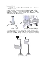
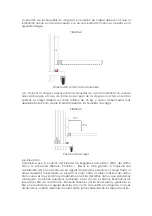
4.2.- Getting the legs out of its support for transport (S) and inserting them in its lodges of 

work (V) verifying that they are left in depth and fasten for the retaining security triggers 
(R). It must dispose long paws on the front part and the short paws on the rear end.


SEE FIGURE 1. 

Summary of Contents for T-109

Page 1: ...T 109 TORRE ELEVADORA MANUAL DE INSTRUCCIONES E ELEVATOR TOWER OPERATING INSTRUCTIONS GB TRAVERSENLIFT BEDIENUNGSANLEITUNG D...

Page 2: ......

Page 3: ...N1 N2 W Q H P V S R F J U L T R1 N1 N2 W N1 N2 N1 N2 W Q H P Q H P V S R F J U L T R1...

Page 4: ...A B T 109 016 T 109 004 A B T 109 016 T 109 004...

Page 5: ...012 T 109 016 T 109 001 T 109 014 ACC 26 ACC 29 T 109 009 T 109 010 C T 108 031 T 109 033 T 109 015 T 109 011 T 109 006 T 109 034 T 109 005 T 109 007 ACC 13 ACC 21 ACC 18 T 109 013 T 109 012 T 109 016...

Page 6: ...CC 26 T 109 002 T 109 026 ACC 26 T 109 020 T 109 017 T 109 020 B T 109 029 T 109 003 T 109 033 A ACC 26 T 109 002 T 109 026 ACC 26 T 109 020 T 109 017 T 109 017 T 109 020 B T 109 029 T 109 003 T 109 0...

Page 7: ...T 109 018 T 109 032 T 109 019 T 109 026 T 109 021 T 109 022 T 109 027 T 109 018 T 109 032 T 109 019 T 109 026 T 109 021 T 109 022 T 109 027 T 109 027...

Page 8: ...T 109 017 T 109 025 T 109 028 T 109 004 T 109 034 T 109 017 T 109 017 T 109 025 T 109 028 T 109 004 T 109 034...

Page 9: ...T 109 024 ACC 14 002 ACC 14 001 ACC 14 ACC 14 002 T 109 024 ACC 14 003 ACC 14 003 C T 109 024 ACC 14 002 ACC 14 002 ACC 14 001 ACC 14 ACC 14 002 T 109 024 ACC 14 003 ACC 14 003 C...

Page 10: ...nima elevable de 25 Kg 2 3 Altura m xima 7 9 m 2 4 Altura m nima 2 00 m Altura m nima para la carga 0 20 m 2 5 rea de la base 2 17 x 1 83 m 2 6 rea de la base cerrada 0 57 x 0 68 m 2 7 Peso 237 Kg 2...

Page 11: ...ido y acabado anodizado tambi n en color negro 2 17 Dispositivo de conexi n de toma a tierra ACC 29 2 18 Ruedas direccionales para el transporte de la torre en posici n vertical y plegada hasta su emp...

Page 12: ...n caso de ser necesario se deber conectar la torre a tierra a trav s del dispositivo de conexi n habilitado para ello ACC 29 3 6 No usar escaleras encima de la torre ni apoyarlas en ella 3 7 Cuidado c...

Page 13: ...e la parte frontal y las patas cortas sobre la parte trasera FIGURA 1 Introducir las Patas Comprobar los Gatillos de Seguridad 4 3 Ajustar la posici n vertical de la torre mediante los platillos de ap...

Page 14: ...a U quitando los pasadores L y colocarlos en posici n para soportar la carga Colocar los pasadores de seguridad FIGURA 3 Desbloquear Gatillo R1 Quitar los pasadores L Sacar las horquillas de carga U P...

Page 15: ...e la carga 4 6 Elevaci n Comprobar que la posici n del Sistema de Seguridad Autom tico SSA del ltimo tramo se encuentra liberado Posici n 1 Elevar la torre girando la manivela del cabestrante W en el...

Page 16: ...cabrestante y elevaci n del carro Altura m xima del carro sobre el ltimo tramo Bloquear SSA del ltimo tramo Posici n 2 SSA bloqueado Liberaci n SSA Tramo Intermedio Paso 1 Liberaci n SSA Tramo Interm...

Page 17: ...d de cada tramo FIGURA 7 Posici n de la torre elevada La torre puede dejarse en cualquier posici n intermedia que se necesite ajustando la altura a uno de los alojamientos del Sistema de Seguridad Se...

Page 18: ...vayan bajando los diferentes tramos hasta que la torre quede completamente plegada a su altura m nima Teniendo en cuenta de mantener sujeto cada SSA conforme se van bajando los tramos FIGURA 8 Giro de...

Page 19: ...mos Hay que bloquear todos los tramos con los SSA y el carro hay que fijarlo mediante el Gatillo de Seguridad R1 Desmontar las patas liberando los gatillos de retenci n y colocarlas en su posici n de...

Page 20: ...han sido engrasados con una grasa especial resistente al calor y la presi n No deben ser utilizados otros productos distintos al original suministrado por la empresa para evitar influir negativamente...

Page 21: ...a sujetacable Acero Zincado Negro T 109 021 Polea nylon Nylatron Nylatron T 109 022 Juego tornillo polea nylon Acero Zincado T 109 023 Tapon Nylon Nylon Blanco T 109 024 Usillopata Zamak Zamak T 109 0...

Page 22: ...ures and gadgetry of illumination 2 1 Max load 320 kg 2 2 Min load 25 kg 2 3 Max height 7 9 m 2 4 Min height 2 00 m Minimal height for the load 0 20 m 2 5 Base area 2 17 x 1 83 m 2 6 Folded base area...

Page 23: ...not use stairs upon the tower neither lean them in it 3 7 Be careful with cables prominent objects etc placed above the tower 3 8 Do not stay under the load 3 9 Do not move the tower when it is lifte...

Page 24: ...blocked Position 1 Lift the tower turning the winch s handle in clockwise N1 raising the load to the required height At the beginning the carriage will lift until the maximum height of the last profil...

Page 25: ...recommended greasing periodically according to the use the crown wheel of the winch pads of the axle of actuating and the bushing the thread of the handle and the profiles of the tower ATTENTION Do no...

Page 26: ......

Page 27: ...y fabricaci n han sido tenidos en cuenta tanto en su totalidad como parcialmente los aspectos recogidos en las normas armonizadas siguientes UNE EN ISO 12100 1 2004 Seguridad de las m quinas Conceptos...

Reviews: