background image

This Manual is Designed to Make it as Easy as Possible for You

to Assemble, Install, Operate, and Maintain Your Ceiling Fan

Unpacking Instructions

For your convenience, check-off each step.  As each step is completed, place a check mark.  This will ensure that all 
steps have been completed and will be helpful in 

fi

 nding your place should you be interrupted. 

Wiring outlet box and box connectors must be of type 

required by local code.  The minimum wire would be a 3-

conductor (2-wire with ground) of the following size:

NOTE:

  Place the parts from the loose parts bags in a small 

container to keep them from being lost.  If any parts are missing, 

contact your local retailer.

Tools Needed for Assembly

Materials

Wire Size A.W.G.

Installed Wire Length

14

12

Up to 50 ft.

50 - 100 ft.

NOTE:

  If you are uncertain of part description, refer to

exploded view illustration. (Figure 1, page 13)

3

1. 

Check to see that you have received the following 

parts: 

• Fan Motor assembly

• Hanger Bracket

• Downrod/Hanger Ball

  assembly

• Ceiling Canopy

• Motor Coupling Cover

• Switch Cup Assembly

• C28 Remote Control

• Receiver Unit

Receiver Unit

Switch Cup

Assembly

Fan Motor Assembly

Downrod/

Hanger Ball

Assembly

Hanger Bracket

• One Phillips head screwdriver
• One stepladder
• One ¼

˝

 blade screwdriver

• One wire stripper


Three wire connectors

  (supplied)

Ceiling Canopy

• Hardware bag:

  – Two 5/32

˝

 threaded rods

  – Two 5/32

˝

 lockwashers

  – Two knurled knobs

  – Three screws, 5/32-32 x 3/8

˝

  – Seven wire nuts

  – Phillips screwdriver, 4

˝

WARNING

Do not install or use fan if any part is damaged or 

missing.  This product is designed to use only those 

parts supplied with this product and/or any accessories 

designated specifically for use with this product by 

Fanimation.  Substitution of parts or accessories not 

designated for use with this product by Fanimation could 

result in personal injury or property damage.  Contact 

your retail store for missing or damaged parts.

WARNING

Before assembling your ceiling fan, refer to section on 

proper method of wiring your fan (page 4).  If you feel you 

do not have enough wiring knowledge or experience, 

have your fan installed by a licensed electrician.

C28 Remote Control

Motor

Coupling

Cover

Hardware Bag

Summary of Contents for The Air Shadow FP820CH

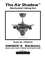
Page 1: ...OWNER S MANUAL READ AND SAVE THESE INSTRUCTIONS Model No FP820CH Net Weight 9 14 kg 20 lbs The Air Shadow Mechanical Ceiling Fan...

Page 2: ...iable for incidental consequential or special damages arising out of or in conjunction with product use or performance except as may otherwise be accorded by law This warranty gives you special legal...

Page 3: ...l assembly Ceiling Canopy Motor Coupling Cover Switch Cup Assembly C28 Remote Control Receiver Unit Receiver Unit Switch Cup Assembly Fan Motor Assembly Downrod Hanger Ball Assembly Hanger Bracket One...

Page 4: ...l the curved portion of the hairpin clip snaps around the clevis pin The hairpin clip must be properly installed to prevent the clevis pin from working loose Pull on the Downrod to make sure the clevi...

Page 5: ...ely tighten the two 3 16 24 x 3 8 setscrews in the downrod support Figure 2 NOTE The setscrews must be properly installed as described above or fan wobble could result 10 Slide the Motor Coupling Cove...

Page 6: ...gure 3 Figure 2 Figure 1 Outlet Box Hanger Bracket Outlet Box Hanger Bracket Screw 2 Supplied with Outlet Box Tab Floor No less than 7 ft Downrod Hanger Ball Assembly WARNING The fan must be hung with...

Page 7: ...to BLACK supply wire WHITE Receiver Unit wire AC IN N to WHITE supply wire WHITE Receiver Unit wire TO MOTOR N to WHITE fan wire BLACK Receiver Unit wire TO MOTOR L to BLACK fan wire BLUE Receiver Un...

Page 8: ...sing water cleansers or harsh rags which can warp and ruin the blade and the finish CAUTION Do not use water when cleaning your ceiling fan It could damage the motor or the finish and create the possi...

Page 9: ...tight 2 Check to make sure wire connectors in switch housing are not rattling against each other or against the interior wall of the switch housing CAUTION Make sure main power is turned off 3 Some fa...

Page 10: ...Motor Coupling Cover P81090 5 Fan Motor Housing Assembly 6 Switch Cup Assembly AP82021 7 Remote Control C28 8 Control Receiver RECCAN57DEMO 9 Hardware Bag s Containing HDWFP820 5 32 32 x 3 8 Screw 3 P...

Page 11: ...11 NOTE The illustration shown is not to scale or its actual configuration may vary The Air Shadow Fan FP820CH Exploded View 4 1 Figure 1 3 2a 7 5 2b 2c 2d 2 8 9 6...

Page 12: ...10983 Bennett Parkway Zionsville IN 46077 888 567 2055 FAX 866 482 5215 Outside U S call 317 733 4113 Visit Our Website www fanimation com Copyright 2007 Fanimation 2007 01...

Reviews: