background image

1.

  Using the 

3

»

8

Ý

 x 2

Ý

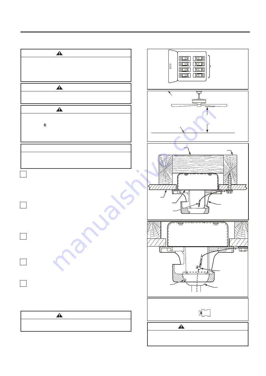
 lag bolt and flat washer, attach 

safety cable to ceiling joist or wood structural member. 
The lag bolt will pass through the flat washer, safety 
cable loop, and into the building structure (Figure 3). 

<RXZLOOILUVWGULOODóÝSLORWKROHLQWRWKHEXLOGLQJVWUX

cture 

to prevent splitting or cracking.

2.

  Securely attach the hanger bracket to ceiling junction 

box

acceptable for ceiling fan support.

NOTE:  Ceiling support cable cannot be secured to 
junction box only, it must be directly secured to ceiling 
joist or structural member 

using the 

ǪÝ

 x 2

Ý

 lag bolt and 

À

 at washer.

  (Figure 3)

3.

  Make sure the electrical supply wires, including the 

hanger bracket grounding wire and safety cable, are 
pulled through the downrod, between the hanger bracket 
and the junction box so that electrical connections can be 
made later. 

  Carefully lift the fan and seat the downrod/hanger ball 

assembly on the hanger bracket that was just attached to 
the ceiling joist.  Be sure the groove in the ball is lined up 
with tab on the hanger bracket. (Figure 4)

5.

  Attach the safety cable to ceiling support cable. Slide 

cable clamp onto safety cable (from fan). Place the end 
of cable through the loop of ceiling support cable. Pull as 
much cable through loop as possible. Feed end of cable 
into clamp hole and firmly tighten screw (Figure 4). Cut 
off excess safety cable.

Ý

Ý

r

r. 

r


Ý

Ý

À

 r.

r. 


of

4.

WARNING

The fan must be hung with at least 7´ of clearance from    
floor to blades. (Figure 2)

WARNING

The outlet box must be securely anchored and capable 
of withstanding a load of at least 35 lbs.  Hanger bracket 
must seat   rmly against outlet box.  If the outlet box is 
recessed, remove wallboard until bracket contacts box. 
If bracket and/or outlet box are not securely attached, 
the fan could wobble or fall.

CAUTION

Do not connect fan blades until the fan is completely 
installed.  Hanging fan with blades connected may result 
in damage to the fan blades.

WARNING

To avoid possible electrical shock, be sure electricity is 
turned off at the main fuse box before hanging. (Figure 1)
NOTE: If you are not sure if the outlet box is grounded, 
contact a licensed electrician for advice, as it must be 
grounded for safe operation.


WARNING

Failure to seat tab in groove could cause damage to 
electrical wires and possible shock or fire hazard.


Figure 2

%'+.+0)

(.114

01.'55

6*#0

(''6

Figure 1

/#+0(75'$1:

911&/'/$'4
r:r#2241:

%'+.+0),1+56

%'+.+0)

,70%6+10 

$1:

*#0)'4$4#%-'6

% ' + . + 0 )
5722146

%#$.'

Figure 3

:

HARDWARE USED:

Figure 4

6#$

016'5722.;9+4'5#0&(#0
9+4'51/+66'&(14%.#4+6;

&19041&*#0)'4
$#..#55'/$.;

#66#%*5#('6;
%#$.'61%'+.+0)
5722146%#$.'

%'+.+0)5722146

%#$.'%.#/2
95%4'9

To avoid possible shock, do not pinch wires 
between the downrod/hanger ball assembly and the 
hanger bracket.

WARNING

8

How to Hang Your Ceiling Fan

Summary of Contents for SCULPTAIRE FP8511 Series

Page 1: ...THESE INSTRUCTIONS Serial Number Purchase Date Espa ol p 19 MODEL FP8511 CEILING FAN Questions problems missing parts Before returning to your retailer call our customer service department at 1 888 5...

Page 2: ...r s manual and safety information before installing your new fan Review the accompanying assembly diagrams 2 Before servicing or cleaning unit switch power off at service panel and lock service panel...

Page 3: ...or any accessories designated specifically for use with this product by Fanimation Substitution of parts or accessories not designated for use with this product by Fanimation could result in personal...

Page 4: ...C 60 HZ 15 Amp Circuit Electrical code requires use of a fan rated outlet box to support the extra weight and motion associated with a ceiling fan A fan rated box will be labeled as such and typically...

Page 5: ...een two joists and takes the place of wooden blocking To avoid fire or shock follow all wiring instructions carefully Any electrical work not described in these instructions should be done or approved...

Page 6: ...top of the motor Install the clevis pin by aligning the holes in the downrod support with holes in the downrod Secure clevis pin with hairpin clip Install and tighten the two set screws with nuts in...

Page 7: ...the end of each lead wire Figure 7 NOTE All set screws must be checked and retightened where necessary before installation 6 Reinstall the hanger ball on the downrod as follows Route the black white a...

Page 8: ...gh loop as possible Feed end of cable into clamp hole and firmly tighten screw Figure 4 Cut off excess safety cable r r r r r of 4 WARNING The fan must be hung with at least 7 of clearance from floor...

Page 9: ...leads upward and carefully push leads into the outlet box with the white and green leads to one side of the box and the black leads to the other side Figure 4 CAUTION INCORRECT WIRE CONNECTION WILL D...

Page 10: ...side the canopy housing and not pinched between the housing and the ceiling Figure 1 Figure 2 How to Assemble Your Ceiling Fan Blades 1 Position the blade over the blade holder of motor assembly with...
Page 11: ...slots in the light plate assembly Replace the third screw and secure all three screws Figure 5 1 Remove one of the three screws in the support bracket at the bottom of the motor assembly Retain the s...

Page 12: ...ce facility for examination or repair CAUTION 6 For use with light kit Remove the three screws in the light plate assembly and retain the screws for Step 8 Figure 6 7 Connect the 2 single pin connecto...

Page 13: ...not use a full range dimmer switch to control the fan speed Figure 1 WARNING Do not operate this fan with a variable Rheostat wall controller or dimmer switch Doing so could result in damage to the c...

Page 14: ...KRXOG EH DYRLGHG WR SUHYHQW GDPDJH Wo ILQLVK 3HULRGLF OLJKW GXVWLQJ RI WKH EODGHV LV UHFRPPHQGHG A IHDWKHU GXVWHU ZLOO ZRUN EHVW AYRLG using ZDWHr FOHDQVHUV or KDUVK UDJV ZKLFK FDQ ZDUS DQG UXLQ WKH E...

Page 15: ...1404 AMA8511 7 Switch Housing Assembly Light Plate Assembly AP851103CL 16 HDWFP8511 12 14 Light Kit Wire Cover With Screw TR500 Hand Held Remote 15 RCCA05005000 Receiver Unit AP845813BL 13 Steel Cap P...

Page 16: ...i t a r u g i f n o c s t r a p l a u t c a s t i r o e l a c s o t t o n s i n w o h s n o i t a r t s u l l i e h T y 16 1 2 3 7 6 5 16 4 Model FP8511 Exploded View Illustration SculptAire 16 16 10...

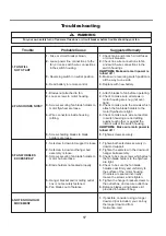
Page 17: ...ews securely 1 Blades not attached to fan 2 Loose screws in motor housing 3 Screws securing fan blade holders to motor flywheel are loose 4 Wire connectors inside housing rattling 5 Screws holding bla...

Page 18: ...Copyright 2019 Fanimation 2019 01 V 01 10983 Bennett Parkway Zionsville IN 46077 Phone 888 567 2055 Outside U S 317 733 4113 FANIMATION COM FAX 866 482 5215...

Page 19: ...CCIONES Peso neto 8 22 kg 18 11 lbs Preguntas problemas piezas faltantes Antes de volver a la tienda llame a nuestro Departamento de Servicio al Cliente al 1 888 567 2055 8 a m 5 pm hora del Este de l...

Page 20: ...icista autorizado para instalar el ventilador PARA REDUCIR EL RIESGO DE DESCARGAS EL CTRICAS ESTE VENTILADOR SE DEBE INSTALAR CON UN CONTROL INTERRUPTOR DE PARED AISLADO 6 El dispositivo no ha sido di...

Page 21: ...o consulte la secci nsobreelm todocorrectodeinstalaci nel ctricadel ventilador p gina 29 Si siente que no posee la experiencia o los conocimientos el ctricos necesarios contrate a un electricista auto...

Page 22: ...ilateur si l une de ses pi ces est endommag e ou manquante Ce produit est con u pour utiliser uniquement les pi ces l accom pag nant et ou les accessoires sp cifiquement con us pour ce produit par Fan...

Page 23: ...ara asegurar un rendimiento eficiente del producto Apague el ventilador cuando no se encuentre en la habitaci n Los ventiladores son para refrescar a la gente no a las habitaciones Si la habitaci n es...

Page 24: ...NCIA A fin de evitar incendios o descargas el ctricas siga con cuidado todas las instrucciones de instalaci n el ctrica Cualquier trabajo el ctrico que no se describa en estas instrucciones deber ser...

Page 25: ...ezas Instale la clavija de horquilla y aseg rela con la pinza de horquilla Instale los set de tornillos con tuercas en el soporte de la varilla Fije con seguridad el set de tornillos con el destornill...

Page 26: ...era Pase el pasador a trav s de los dos orificios en el barral y alinee la semiesfera de modo que el pasador quede atrapado en la ranura de la parte superior de la misma Empuje la semiesfera hacia arr...

Page 27: ...te de suspensi n y la caja de conexiones de modo que m s tarde se pueda realizar la instalaci n el ctrica AVERTISSEMENT La bo te de sortie doit tre solidement ancr e et acceptable pour supporter un ve...

Page 28: ...dor y coloque el ensamble de la bola para colgar varilla en la abrazadera para colgar que acaba de fijar a la caja de salida Aseg rese de que la ranura de la bola est alineada con la leng eta de la ab...

Page 29: ...e el conductor azul de la unidad receptora al conductor azul de la iluminaci n del ventilador con el conector de cables que se adjunta con la unidad receptora Figura 3 Interruptores Unidad del recepto...

Page 30: ...ba y completamente empujarse con cuidado en el cuadro de juntura y de que no est n aprisioel techo AVERTISSEMENT Pour viter tout risque d incendie ou de choc assurez vous que les fils lectriques sont...

Page 31: ...e lesiones personales no doble los soportes de aspas al instalarlos balancear las aspas o limpiar el ventilador No coloque objetos extra os entre las aspas del ventilador en funcionamiento ADVERTENCIA...

Page 32: ...los tres tornillos Figura 5 1 Retire uno de los tres tornillos en la placa del adaptador en la parte inferior del ensamble del motor gu rdelos para despu s y afloje ligeramente los dos tornillos resta...

Page 33: ...f jela con el tornillo suministrado Figura 10 Figura 10 NOTA Si ha instalado su ventilador con la tapa de acero s ltese los pasos 6 7 8 a 9 A fin de reducir el riesgo descargas el ctricas desconecte...

Page 34: ...o en los conectores de cables con la excepci n del cable de toma de tierra No utilice el ventilador hasta que las palas est n colocadas en su lugar ya que de lo contrario se podr a causar ruido y da o...

Page 35: ...la carcasa del interruptor gir ndola en el sentido de las agujas del reloj Figura 6 mando a distancia Mueva los interruptores de c digo hasta colocar el c digo de selecci n en la posici n arriba o ab...

Page 36: ...comienda limpiar el polvo de las aspas peri dicamente Lo mejor es utilizar un plumero Mantenimiento El nico mantenimiento necesario para el ventilador de techo es una limpieza peri dica Al llevar a ca...

Page 37: ...de iluminaci n AP851103CL 16 HDWFP8511 12 14 Cubierta de cables del kit de iluminaci n TR500 Mano a distancia 15 RCCA05005000 Unidad del receptor AP845813BL 13 Tapa de acero P851107 8 9 Juego de aspas...

Page 38: ...38 1 2 3 7 6 5 16 4 FP8511 Ilustraci n del despiece SculptAire 16 16 10 8 9 12 11 13 15 14 NOTA La ilustraci n que se muestra no est hecha a escala y sucguraci nrealy oterminaci n puede variar...

Page 39: ...uste bien los dos tornillos de fijaci n y las tuercas en el soporte de barral 2 Ajuste el tornillo de fijaci n en la unidad del barral de la semiesfera 3 Aseg rese de que los tornillos que fijan los s...

Page 40: ...ro sitio Web en www fanimation com 10983 Bennett Parkway Zionsville IN 46077 Llame sin cargo al 888 567 2055 FAX 866 482 5215 Desde fuera de los EE UU llame al 317 733 4113 Copyright 2019 Fanimation 2...

Reviews: