Fanimation HF7000 Series Owner'S Manual Download Page 6

6

Clevis Pin

Setscrew (2)

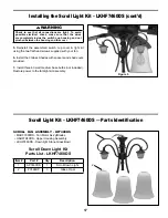
How to Assemble Your Ceiling Fan

Pin

Setscrew

Hanger

Ball

Figure 1

1. 

Prior to assembly, set aside and save the hardware 

bag(s) packed in the packing.

2. 

Remove the Hanger Ball by loosening the setscrew 

in the Hanger Ball until the ball falls freely down the 
Downrod. (Figure 1)  Remove the Pin from the Downrod, 
then remove the Hanger Ball.  Retain the Pin and Hanger 
Ball for reinstallation in Step 8.

3. 

The fan comes with support cable, black and white 80

˝


wires. Separate and untwist the wires & cable. Route the 
wires & cable through the Downrod.

NOTE: 

 You will be using either the 6

˝

 downrod supplied with 

your fan or an optional downrod purchased separately.

4.

 Position Fan/Motor Assembly on styrofoam, for ease of 

assembly. 

5.

 Loosen the two setscrews in the Downrod Support.  Align 

the Clevis Pin holes in the Downrod with the holes in the 
Downrod Support.  Install the Clevis Pin and secure with 
the Hairpin Clip. (Figure 2)  Be sure to push the straight 
leg of the hairpin clip through the hole near the end of the 
clevis pin until the curved portion of the hairpin clip snaps 
around the clevis pin.  The hairpin clip must be properly 
installed to prevent the clevis pin from working loose. Pull 
on the Downrod to make sure the clevis pin is properly 
installed. (Figure 2)

6. 

While pulling up on the hanger ball, securely tighten 

the two 3/16-24 x 3/8

˝

 setscrews in the downrod support. 

(Figure 2)

7.  

Install 3 - 40 watt candelabra bulbs (not included) 

(Figure 3)

NOTE:

 The setscrews must be properly installed as 

described above, or fan-wobble could result.

Figure 2

Hairpin Clip

Downrod 

Support

Figure 3

Summary of Contents for HF7000 Series

Page 1: ...3 lbs WARNING Support Directly From Building Structure For Canada this fan must be secured directly to the building structure or ceiling joist Don t secure this fan to an outlet box Acharn Fan Net Wei...

Page 2: ...eaning unit switch power off at service panel and lock service panel disconnecting means to prevent power from being switched on accidentally When the service disconnecting means cannot be locked secu...

Page 3: ...r One wire stripper Three wire connectors supplied Ceiling Canopy WARNING Do not install or use fan if any part is damaged or missing This product is designed to use only those parts supplied with thi...

Page 4: ...be properly grounded as a precaution against possible electrical shock WARNING To reduce the risk of fire electrical shock or personal injury mount fan to outlet box marked acceptable for fan support...

Page 5: ...gure 3 Collar Figure 4 DR1x18 18 Down Rod Assembly 4 Assemble the 18 Down Rod and the Sleeve Kit in the order as shown Figure 4 Sleeve 4 Collar Figure 5 DR1x24 or Longer 24 or longer Down Rod Assembly...

Page 6: ...bly on styrofoam for ease of assembly 5 Loosen the two setscrews in the Downrod Support Align the Clevis Pin holes in the Downrod with the holes in the Downrod Support Install the Clevis Pin and secur...

Page 7: ...Hanger Ball Assembly Figure 6 Downrod Support Figure 5b Figure 5a 8 The three screws are pre assembled onto the Fan Motor assembly Figure 4 Remove three screws and use them to attach the Housing Fixtu...

Page 8: ...s omitted for clarity 1 Using the 3 8 x 2 lag bolt and flat washer attach safety cable to ceiling joist or wood structural member The lag bolt will pass through the flat washer safety cable loop the j...

Page 9: ...cover off Slide code switches to your choice of up or down position Factory setting is all up Do not use this position With a small screwdriver or ball point pen slide firmly up or down Figure 1a Rep...

Page 10: ...ng the Fan Blades 1 Lay blade holder with the threaded posts facing up 2 Position the wood blade over the blade holder with the threaded posts showing through the holes of the blade 3 With a Phillips...

Page 11: ...the Receiver Unit and Switch Cup Housing NOTE This step is applicable for model without lower Light Kits For Acharn or Scroll fan models skip this section and go to page 14 or 16 Figure 2 IMPORTANT A...

Page 12: ...Downrod Assembly ADR1x6 3 Downrod Cover Assembly AP7070 4 Ceiling Canopy P7080 7 Fan Motor Assembly AMA7000 8 Blade Holder Set 5 AP7030 9 Wood Blade Set 5 Coffee or Slate AP7052 10 Switch Cup Cover As...

Page 13: ...13 NOTE The illustration shown is not to scale or its actual configuration may vary Decorative Uplight Fan HF7040 Exploded View also for Acharn Scroll Fans 4 1 Figure 1 3 6 5 2 7 13 12 11 8 9 10...

Page 14: ...fixture unit on switch cup cover with lockwasher and nut provided 3 Locate white and blue wires labeled FOR LIGHT Securely connect white to white and blue to black wires as shown Push the connectors u...

Page 15: ...assembly WARNING Check to see that all connections are tight To avoid possible electrical shock make sure that the wires are completely inside the switch cup housing and not pinched between the housin...

Page 16: ...ngle light fixture unit on switch cup cover with lockwasher and nut provided CAUTION To avoid possible electrical shock be sure electricity is turned off at the main fuse box before installing light k...

Page 17: ...cont d WARNING Check to see that all connections are tight To avoid possible electrical shock make sure that the wires are completely inside the switch cup housing and not pinched between the housing...

Page 18: ...ht 2 Check to make sure wire connectors in switch housing are not rattling against each other or against the interior wall of the switch housing CAUTION Make sure main power is turned off 3 Some fan m...

Page 19: ......

Page 20: ...ION 10983 Bennett Parkway Zionsville IN 46077 888 567 2055 FAX 866 482 5215 Outside U S call 317 733 4113 Visit Our Website www fanimation com All Hubbardton Forge designs the mark HUBBARDTON FORGE an...

Reviews: