background image

9

Assembling and Mounting the Fan Blades, & Adapter/Switch Hsg

NOTE:


 Shipping Support Plate 

MUST

 be removed prior to 

assembling blades!

Blade & Blade Holder Assembly:
1.

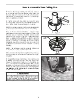
 Lay the side of the blade holder on a flat surface with the 

inside of the blade holder facing up.  This is the side with 
the threaded posts.

2.

 Position the wood blade over the blade holder with the 

threaded posts showing. Make sure the bottom edge of 
the blade is fully seated against the blade holder. 

3.

 With a Philips screwdriver, tighten pan-head screws with 

fiber, and flat washers to secure the blade. (Figure 1)

NOTE:


 The switch cap housing 

must


be removed

 prior 

to installing blade & blade holder assembly to the motor 
hub.

4. 

Attach assembled blades and blade holders to the motor 

hub using the provided screws.


(Figure 2)

5. 

Make sure the screws securing the blade holders to the 

motor hub are tight and that the blade holders are properly 
seated.

Housing Switch Cup/Adapter Assembly:
6. 

Disassemble the Housing Switch Cup/Adapter assembly 

by removing three screws. (Figure 3)

7. 

Assemble the Adapter assembly on the Housing Support 

bracket and tighten three screws. (Figure 4)

8. 

Assemble the Adapter assembly on the Housing Support 

bracket and tighten three screws. (Figure 4)

9. 

Securely attach the 9-pin switch cup connector to wiring 

harness socket within Adapter assembly. (Figure 4)

Figure 2

Fan Blade

Screw

(2 per blade 

holder)

Figure 1

Blade Holder

INSTALLATION NOTE

Do not connect fan blades until the fan is completely 

installed. Installing the fan with blades assembled may 

result in damage to the fan blades.

WARNING

To reduce the risk of personal injury, do not bend the 

blade holders when installing, balancing the blades or 

cleaning the fan. Do not insert foreign objects in between 

the rotating blades.

Figure 4

Figure 3

Summary of Contents for Alamosa FP3820RP

Page 1: ...OWNER S MANUAL READ AND SAVE THESE INSTRUCTIONS Model No FP3820RP The Alamosa Ceiling Fan Net Weight 18 9 kg 42 lbs ...

Page 2: ...rranty gives you special legal rights and you may also have other rights that vary from state to state 10 A certain amount of wobble is normal and should not be considered a problem or a defect LIMITED LIFETIME WARRANTY Extends to the original purchaser of a Fanimation Fan Important Safety Instructions WARNING To avoid fire shock and serious personal injury follow these instructions Table of Conte...

Page 3: ...lders Hardware Bags Fan Motor Hub Assembly Downrod Hanger Ball Assembly Hanger Bracket One Phillips head screwdriver One stepladder One blade screwdriver One wire stripper Three wire connectors supplied Ceiling Canopy Wood Blades Hardware bags Eleven 20 x 14mm blade holder to fan motor hub screws Sixteen 3 16 24 x 15mm blade to blade holder pan head screws fiber flat washers Two 5 32 threaded rods...

Page 4: ...ns carefully Any electrical work not described in these instructions should be done or approved by a licensed electrician WARNING Turning off wall switch is not sufficent To avoid possible electrical shock be sure electricity is turned off at the main fuse box before wiring All wiring must be in accordance with National and Local codes and the ceiling fan must be properly grounded as a precaution ...

Page 5: ...nd the clevis pin The hairpin clip must be properly installed to prevent the clevis pin from working loose Pull on the Downrod to make sure the clevis pin is properly installed NOTE The setscrews must be properly installed as described above or fan wobble could result 4 Route wires and safety cable through opening in Canopy Position Canopy on fan shown with open side facing up Figure 4 5 Reinstall...

Page 6: ...lue black and white leads Before installing fan measure up approximately 6 9 inches above top of Downrod Hanger Ball Assembly Cut off excess wire and strip back insulation from end of wire 8 You have now completed the upper assembly of your new ceiling fan You can now proceed with the hanging and the electrical wiring of your fan Ceiling Canopy Downrod Hanger Ball Assembly Figure 4 ...

Page 7: ...t Ceiling Downrod Hanger Ball Assembly Attach Safety Cable to Ceiling Support Cable Tab NOTE Supply wires and fan wires omitted for clarity 1 Using the 3 8 x 2 lag bolt and flat washer attach safety cable to ceiling joist or wood structural member The lag bolt will pass through the flat washer safety cable loop the junction box and into the building structure Figure 2 You will first drill a pilot ...

Page 8: ...Box Black Green Wire Ground from Hanger Bracket Green Wire Ground Black Fan Wire White Blue Green Wire Ground from Hanger Bowl Figure 1 WARNING To avoid possible electrical shock be sure electricity is turned off at the main fuse box before wiring NOTE If you are not sure if the outlet box is grounded contact a licensed electrician for advice as it must be grounded for safe operation WARNING Check...

Page 9: ...e sure the screws securing the blade holders to the motor hub are tight and that the blade holders are properly seated Housing Switch Cup Adapter Assembly 6 Disassemble the Housing Switch Cup Adapter assembly by removing three screws Figure 3 7 Assemble theAdapter assembly on the Housing Support bracket and tighten three screws Figure 4 8 Assemble theAdapter assembly on the Housing Support bracket...

Page 10: ...box by turning the electricity on at the main fuse box 2 Check the operation of the fan by gently pulling on the pull chain switch Figure 2 3 If airflow is desired in the opposite direction turn the fan off and wait for the blades to stop turning Then slide the reverse switch to the opposite position and turn fan on again Your fan model is equipped with a 4 position 3 speed pull chain switch The o...

Page 11: ...lders to the motor flywheel are tight 4 Check to make sure wire connectors in switch housing are not rattling against each other or against the interior wall of the switch housing CAUTION Make sure main power is turned off 5 Some fan motors are sensitive to signals from solid state variable speed controls Solid state controls are not recommended choose an alternative control method 6 Tighten screw...

Page 12: ...pport Cable Bag Containing HWBSCABLE Ceiling Support Cable Cable Clamp Flat Washer Lag Bolt 3 8 x 2 6 Hardware Bag Containing HDWFP3820 5 32 Threaded Rods 2 5 32 External Lockwasher 2 Knurled Knobs 2 L Screwdriver Chain Coupler Chain Fob Wire Connectors 4 7 Blade Holder Mounting Hardware Bag Containing HDWBH3820 20 x 14 mm Phillips Screws 11 8 Blade Mounting Hardware Bag Containing HDWBM3820 Wood ...

Page 13: ...7 6 5 The Alamosa FP3820RP Exploded View 4 1 3 2a 2b 2c 2d 2 NOTE The illustration shown is not to scale or its actual configuration may vary Figure 1 8 9 10 11a 11 4a 13 ...

Page 14: ...10983 Bennett Parkway Zionsville IN 46077 888 567 2055 FAX 866 482 5215 Outside U S call 317 733 4113 Visit Our Website www fanimation com Copyright 2007 Fanimation 2007 01 ...

Reviews: