background image

PAGE: 6 / 8

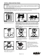
Tuck  all  wires  into  the  canopy.  Push  the  canopy  upwards, 
lining  up  the keyholes  on  the  bottom  with  the  screws  on 
the  hanger  bracket.  Twist  the  Canopy  to  lock  it  in place, 
then tighten the screws to secure it. 
Attach the decorative cap up to the canopy to cover the 
screws.

Thread the blade screws through the 
holes in the blade holder and the holes 
in the blade, and into the decorative 
plates. Tighten all screws securely. 
Repeat with other blade.
Note: Place the blade holders onto the 
blades properly according to the marks 
respectively labeled on the blade holders 
and blades.

Green (Ground)

Fig.8

Secure blade holders to the motor 
with motor screws.

Fig.10

Screw

Canopy

Decorative Cap

Blade Screw

Blade Holder

Blade 

Decorative Plate

Fig.11

Fig.12

Motor Screw

Blade Holder

Fig.13

Switch Box Screw

Switch Box Cover

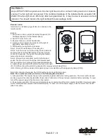
Make wire connections: 
1). The white motor wire to the white wire from the outlet box with a wire nut.
2). The black motor wire to the black wire from the outlet box with a wire nut.   
3). The ground wire from the outlet box to the ground wire from the motor
      with a wire nut. 
***  After making the wire connections, the wires should be spread apart with the 
      grounded wires on one side of the outlet box and the ungrounded wires on the 
      other side of the outlet box.
***  After the connections have been made, the wires should be turned upward and 
      pushed carefully up into the outlet box.

Make sure the wires of the fan light in 
the switch box are capped with wire 
nuts. Secure the switch box cover with 
the switch box screws.

140116

F      A      N                     C       O

F      A      N                     C       O

Fig.14

Turn ON the electric power at the
main fuse or circuit breaker box.

Hang the safety cable into the safety cable 
hook.( See Fig.9)

Fig. 9

Safety Cable Hook

Safety 
Cable

Summary of Contents for aireRyder F0014

Page 1: ...ion services If the original purchaser ceases to own the Fan this warranty and any implied warranty including but not limited to any implied warranty of merchantability or fitness for a particular pur...

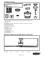
Page 2: ...Cover 5 Blade Holder 5 PCS 6 Decorative Plate 5 PCS 7 Housing 8 Fan Blade 5 PCS 9 Switch Box Cover 10 Decorative Cap 11 Assembly Kit 12 Installation Instructions 13 Balancing Kit Package Contents E C...

Page 3: ...rees Exploded View Detail Dual Mount Drawing Hanger Bracket Canopy Downrod Downrod Stand Cover Hanger Ball Collar Lock Pin Housing Switch Box Cover Hanger Pin Blade Holder Blade 140116 F A N C O F A N...

Page 4: ...o cover all possible conditions and situations that may occur It must be understood that common sense caution and care are factors which can not be built into this product These factors must be suppli...

Page 5: ...r Slide Hanger Pin through holes of Collar and Downrod Fig 6 Lock Pin Collar Screws Slot Chip Hanger Bracket Fig 7 Hanger Pin Lock Pin Fig 3 Motor Wires Downrod Downrod Stand Cover Canopy Fig 4 Remove...

Page 6: ...crew Blade Holder Fig 13 Switch Box Screw Switch Box Cover Make wire connections 1 The white motor wire to the white wire from the outlet box with a wire nut 2 The black motor wire to the black wire f...

Page 7: ...tungsten lamps not compatible with energy saving lamps CFL Note After changing the blades the CODE setting has to be performed again Note The receiver provides protection in the following two situatio...

Page 8: ...eighed and grouped by weight Natural woods vary in density which could cause the fan to wobble even though all blades are weight matched The following procedures should eliminate most of the wobble Ch...

Page 9: ...o be in line with the other blades After following all the steps and if the wobbling problem is not solved a dynamic balancing needs to be done by balancing kit Follow the procedure listed below Turn...

Reviews: