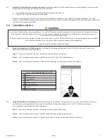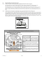
A
C
E
G
F
H
B
D
Anchorage
SRD Integral Swivel Eye
Web Lifeline
Leg End Connector
External Shock Absorber
Dorsal D-ring on FBH
Carabiner
SRD Body/Housing
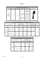
Figure 4:
Attaching Single-leg FT-X to Anchor
102022
MSRD26 Rev B
8
5.3
Attaching to an Anchorage
Examine the work area for possible hazards. Take caution to avoid overhead hazards such as cranes, poles, overhead power cables, and
walking/working surface hazards such as power cables, welding leads, air and fluid hoses, including obstruction hazards such as vertical
columns and stacks of materials on the lower level. Eliminate hazards where possible.
Ensure the anchorage provides the Minimum Required Fall Clearance (MRFC) in the fall path below the walking/working surface to
prevent striking the lower level or an obstruction during a fall event. Take action to avoid swing falls, which occur when the anchorage is
not directly above the point where the fall occurs.
Fall clearance and swing falls are subject to variable conditions. Anchor height, lateral movement, and setback distance all affect anchor
location with regard to fall clearance and swing falls.
The SRL may be attached to an overhead anchor, i.e., above the user’s FBH dorsal D-ring, or a non-overhead anchor, i.e., below the user’s
FBH dorsal D-ring. A non-overhead anchor may be a maximum of 5’ (1.5 m) below the user’s FBH dorsal D-ring for a worker weighing
130 to 310 lbs (59 to 141 kg) or a maximum of 3' (0.9 m) below the user's FBH dorsal D-ring for a worker weighing 311 to 420 lbs (141
to 191 kg) . Non-overhead anchor locations result in greater possibility of edge hazards. At no point during a fall shall the lifeline be loaded
over any edge. Use of a below D-ring anchorages should be as a last resort, when no other anchor option exists. When anchored below
the FBH back D-ring, fall events will result in greater fall clearances.
5.4
Using the FT-X Web SRL-P
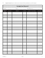
Before each use, inspect the FT-X Web in accordance with Section 7. Remove the device from service if the inspection shows damage
or any malfunction.
Don the FBH and/or attach the SRL in accordance with the harness manufacturer’s instructions.
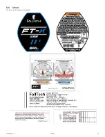
Follow the instructions contained in this manual and on the labels. Failure to follow instructions may result in serious injury or death.
Connect the leg-end connector to an approved anchorage point or to the full body harness depending on orientation. Ensure the
connector closes and locks. Ensure all connections are compatible. Normal operation will allow the working length of the lifeline to extend
and retract as the worker moves about.
Avoid sudden or quick movements during the normal work operation, as this may cause the SRL pawl system to engage and possibly
cause loss of balance, which may cause injury or death. If a fall occurs, the pawl system will engage and lock the lifeline. The EA will
deploy to arrest the fall and limit arrest forces on the user.
5.4.1
Locking Mechanism:
The SRD utilizes an acceleration based locking mechanism. The locking function requires a certain payout rate during
a fall event to function correctly. Certain situations, confined or cramped spaces, shifting footing such as sand, gravel, grain, or a sloped
surface may not allow the lifeline to reach sufficient speed to activate the lock mechanism. A clear path is required to assure positive
locking of the SRD. Ensure the lock is functioning properly. Pull the lifeline out a short distance and give it a sharp tug. The lifeline must
lock. If it fails to lock, remove it from service immediately. Ensure the work zone remains within stated parameters.
5.4.2
Visual Indicator:
The primary fall arrest impact indicator is the energy absorber in the lifeline between the housing and the leg-end
connector. Torn stitching, deployment, expansion, or lengthening of the white internal energy absorber webbing is an indication that a fall
event has occurred and the unit must be removed from service. Remove from service any unit that fails inspection, including inspection of
the fall arrest impact indicator. If you have any questions, contact FallTech.

