FALCON
®
ELECTRIC, INC.
SUP Series
TM
User’s Guide
700-1000VA
WWW.FALCONUPS.COM
800.842.6940
SUP700-1C, SUP1.0K-1C
FALCON® ELECTRIC, INC.
Irwindale, CA 91706
Tel. 626-962-7770
Fax. 626 962-7720
OM48031-SUP, 01/09/04, Rev A.
5116 Azusa Canyon Road
Page 1: ... INC SUP SeriesTM User s Guide 700 1000VA WWW FALCONUPS COM 800 842 6940 SUP700 1C SUP1 0K 1C FALCON ELECTRIC INC Irwindale CA 91706 Tel 626 962 7770 Fax 626 962 7720 OM48031 SUP 01 09 04 Rev A 5116 Azusa Canyon Road ...
Page 2: ...l Diagram Description 9 Chapter 4 Operation 11 Turning The UPS On and Off 11 UPS Self Test 11 UPS Overload Condition 11 DC Start Cold Start 11 Green Mode Function 11 Battery Charging 12 UPS Reset 12 Remote Control 12 Chapter 5 Maintenance Technical Support 13 Care Maintenance 13 Battery Replacement Warning 13 Battery Replacement 13 Storing the UPS and Batteries 14 FCC Considerations 14 Technical S...
Page 3: ... detergent on the UPS Never attempt to service batteries High voltage exists within the unit which could cause electrical shock Servicing of batteries should be performed or supervised by personnel knowledgeable of batteries and the required precautions Keep unau thorized personnel away from batteries When replacing the UPS batteries use the same number and type of batteries Allow at least 24 hour...
Page 4: ...display gives immediate and detailed UPS and power information without having to connect an expensive monitoring computer An intelligent RS 232 computer interface port is also located on the UPS rear panel in the event remote monitoring or unattended computer shutdown is required An optional external SNMP HTTP agent is available giving the ability to manage the UPS remotely across a LAN WAN or via...
Page 5: ...c 50Hz European source verify the connected equipment was designed to operate from a 120Vac 50Hz power source This information is stated on the nameplate label located on the model number label located on rear panel of the unit 3 This UPS has been shipped with the battery connection jumper removed to meet new transportation regulations THE BATTERY CONNECTION JUMPER MUST BE INSTALLED PRIOR TO PLUGG...
Page 6: ...and will open when the utility fails Pins 5 and 4 are normally open and will close at the low battery indication The UPS will shut down when a 5 12 Vdc voltage is applied across Pins 6 and 7 for three seconds while the UPS is on battery mode 6 DO NOT BLOCK UPS AIR VENTS THE UPS MUST NOT BE INSTALLED IN AN ENCLOSED AREA 7 If you have not already done so connect the equipment to be protected to the ...
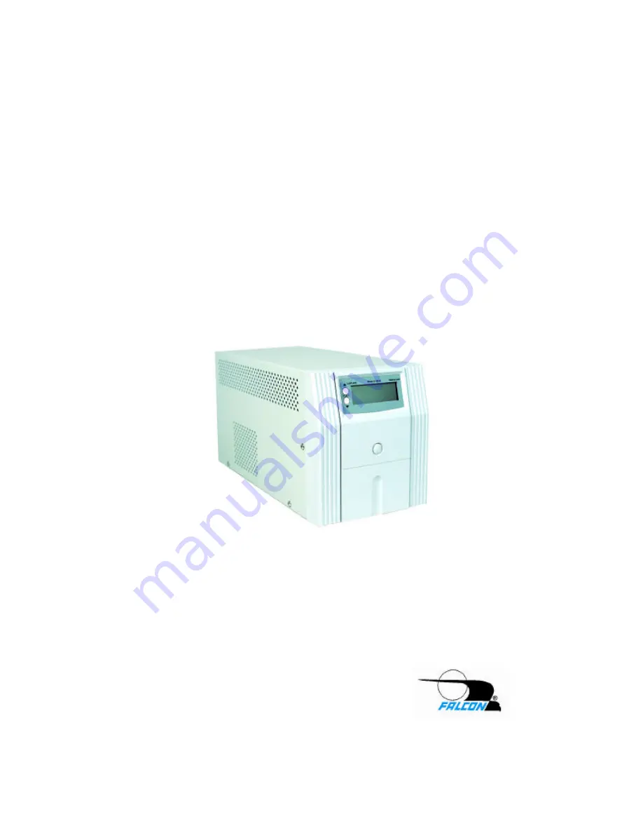
Page 7: ...iquid Crystal Display LCD is provided Please reference the number designation for the display function and the function descriptions referenced in this manual Refer to pages 6 8 in this manual C Two LCD metering function select buttons are provided The upper button scrolls the display through the metering functions in an upward direction the lower button in a downward direction Refer to LCD Meteri...
Page 8: ...Mode The sinewave symbol will be displayed when the UPS is operating normally from the utility line Battery Mode The sinewave and battery symbols will blink when the UPS is operating on its internal battery Test Mode The sinewave symbol will display steadily and the battery symbol will blink during a UPS self test 5 Buck Mode The Automatic Voltage Regulator AVR is reducing the UPS output voltage d...
Page 9: ...60ºC the UPS will shutdown to prevent damage due to excessive overheating 9 Fan off This symbol is used on special extended backup models only 10 Alarm off The audible alarm has been silenced To reset the alarm during backup mode briefly depress the control button 11 UPS fault Attempt to perform a UPS reset by depressing the control button and holding it for ten seconds If the UPS resets and opera...
Page 10: ... will turn on when the display reaches zero Battery Minutes to off The estimated remaining battery run time while in battery backup mode LCD Metering Display Modes use display scroll buttons to change modes modes are in descending order 2 5 4 3 NEMA Type IEC Type Battery Fuse Step 1C Battery Fuses TYPICAL UPS REAR PANEL 1 Battery Disconnect Jumper To install the Jumper use the following procedure ...
Page 11: ...ct the incoming telephone line to one of the jacks Then connect the fax modem or other device to be protected to the other jack 7 Audible Alarms Reference the following table ALARM PERIOD STATUS INDICATED No Beep Utility Good No Beep Utility Loss UPS OFF No Beep LCD flashes every 2 seconds Timer on refer to operation section 9 No Beep Continuously Normal utility good One beep every 4 seconds Opera...
Page 12: ...s if the overload is removed the UPS will automatically turn on again If the overload is still present the UPS will turn off and stay off requiring the UPS be manually restarted Always correct any overload condition immediately 4 DC Start Cold Start To start the UPS when utility power is not available press and hold down the control button twice for one second each time The UPS will start up and r...
Page 13: ...e to a loss of utility power 7 UPS Reset In the event the UPS will not accept commands and appears to be locked up depress the control button for and hold for ten seconds The UPS CPU will be reset 8 Remote Control The UPS can be set for an automatic daily shutdown and start up This command must be set through the RS 232 interface using the supplied software When this function is set a timer inside...
Page 14: ...or computer room environments the batteries should be replaced every three to five years Never attempt to service batteries High voltage exists within the unit which could cause electrical shock Servicing of batteries should be performed or supervised by personnel knowledgeable of batteries and the required precautions Keep unauthorized personnel away from batteries When replacing the UPS batterie...
Page 15: ...rer s instructions may cause interference to radio and television reception All models covered in this manual have been tested and found to comply with the limits for a Class A computing device in accordance with the specifications in FCC regulations Part 15 Subpart J which are designed to provide reasonable protection against such interference If this equipment does cause harmful interference to ...
Page 16: ...ords The RMA number issued must appear on the outside of the shipping carton The original shipping container must be used when returning any SUP Series product Falcon Electric will not assume any responsibility for shipping damage In the event of shipping damage you will be charged for repairs due to the damage All units must be returned prepaid The address and shipping instructions will be given ...
Page 17: ...ing the nature of the trouble experienced and the disposition of the equipment after repair The equipment will be returned freight collect by FALCON to the location specified via the best and least expensive carrier available or via customer s shipping instructions 2 3 During the in warranty period no service charges shall be payable by the buyer for service performed other than for service necess...
Page 18: ...umidity 10 to 95 Non Condensing Cooling Low Velocity Forced Air Fans Audible Noise 1 meter 45dBA Controls and Indicators Control One Main Control Button UPS On Off Self Test Reset Silence Alarms Selection Control Two LCD Metering Scroll Function Select Buttons LCD Display AC Input Voltage AC Output Voltage Output Frequency DC Battery Voltage Internal UPS Temperature Timer Minutes to Shutdown Hours...