

10
SECTION 6 -
OPERATING INSTRUCTIONS
The fryers are of single pan type and the following units
are covered by this manual.
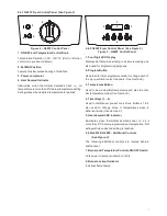
G401F - Manual control model with built-in filtration.
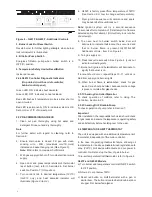
G402F - Four product key electronic control model
with built-in filtration.
USE OF OILS/SHORTENING/SOLIDS
(COOKING MEDIUM)
As these are highly flammable when in their liquid state,
caution should always be taken when using cooking
medium.
Recommendation
PPE (Personal Protective Equipment) should be used
when cleaning or handling medium within this fryer.
Medium should not be overheated as this will increase
the risk of fire.
Note: Fryer is fitted with a thermal safety device. This will
stop heating of medium if it becomes overheated.
This appliance will always fail safe.
Note: NEVER leave a working unit unattended.
Medium must always be maintained within fry pot.
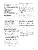
Cold Medium - when filling with cold medium (see Figure
5), DO NOT FILL MEDIUM PAST -MIN- LEVEL MARK
(Maximum cold fill mark) also, for Solid Medium -
See Section 9.
-MIN- Level Mark: Medium should NEVER be allowed to
drop below this mark. Should this occur, top up
immediately or switch fryer OFF.
Hot Medium and
Topping Up Medium
DO NOT FILL MEDIUM
PAST -MAX- LEVEL MARK
(Maximum Hot Fill Mark).
(See Figure 5).
Figure 5
CAUTION: SUITABLE PROTECTIVE CLOTHING
MUST BE WORN when topping up whilst fat in fryer
is hot.
Medium and Foodstuffs
As foodstuffs increase volume during cooking - follow
these rules:
DO NOT ADD WATER TO FRYING MEDIUM AT ANY
TIME!
WARNING
No attempt must be made to operate this appliance
during a power supply failure.
Please ensure that any plastic coated items are removed
prior to use. Before operation, pan requires to be
thoroughly cleaned and dried.
Discolouration of heated parts is caused by factory
testing to ensure unit is satisfactory. It will not affect
quality or performance.
All Models
A neon indicator is incorporated to indicate flame failure
when illuminated.
An electronic thermostat with temperature probe is fitted
to automatically control oil temperature. The burner is
protected by an electronic flame sensor device.
An additional temperature limit thermostat is also fitted,
independent of main thermostat.
Operating thermostat failure could allow oil temperature
to exceed the legislated maximum safe temperature
(230
⁰
C). In such condition, the limit thermostat will
activate and cut power to controller and it will also stop
the flow of gas to burner.
To find location of re-set limit thermostat, refer to
Figure 4 on Page 6 of this manual.
Limit Thermostat Reset
a) Turn burner and temperature controls ON/OFF switch
to OFF position.
b) Allow oil to cool below 180
⁰
C.
c) Unscrew black protective cap from limit thermostat
reset button, button is located behind cabinet door at
upper RH below fascia panel.
d) Reset red button on limit thermostat with a pen or
similar item.
e) Turn burner and temperature controls ON/OFF switch
to ON position.
f) Reselect temperature.
g) If limit thermostat reactivates an investigation to
determine the reason must be carried out by a
qualified technician.
6.1 APPLIANCE CONTROLS
Refer to Sections 2.4.1, 2.4.2 and 2.4.3 for controls
layout and description.
Summary of Contents for G402F
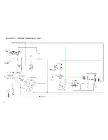
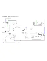
Page 16: ...SECTION 11 WIRING DIAGRAM for G401 16...
Page 17: ...SECTION 11 WIRING DIAGRAM for G401F 17...
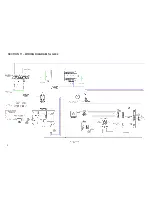
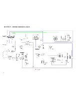
Page 18: ...SECTION 11 WIRING DIAGRAM for G402 18...
Page 19: ...SECTION 11 WIRING DIAGRAM for G402F 19...
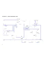
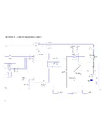
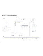
Page 20: ...SECTION 11 CIRCUIT DIAGRAM for G401 20...
Page 21: ...SECTION 11 CIRCUIT DIAGRAM for G401F 21...