


6
7
3
5
1
8
2
9
4
11
5
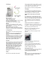
9. Cleaning / Maintenance
Regular cleaning of the fryer will help
prolong its life.
Turn the switch to 0.
Swing the heating element to the "draining"
position (see Fig. 1).
Empty the oil into the receptacle and remove it.
Place a bucket below the drain valve and swing the
element up to its cleaning position (see Fig. 2).
Clean the pan and the element with water and a
recommended detergent. Rinse well and dry.
Caution
Do not use a metal brush to clean the element.
The elements should never be cleaned by running
the unit empty. This will invalidate the guarantee.
The metal parts of the casing are made of stainless
steel and can be cleaned with an appropriate cleaning
product.
The fryer should not be washed with a water jet or
high pressure jet.
10. Electronic Safety Thermostat
The unit is fitted with an electronic safety thermostat
according to the latest regulations.
If the operating thermostat does not work correctly or
if the level of ooil is too low, the safety thermostat will
react at 215°C and automatically cut off the power
supply.
If the safety thermostat stops the machine several
times in succession, call Falcon Service-line.
Notice
The safety thermostat can only be reset after the oil
has cooled down to 190°C.
11. Options
11.1 Oil Pumping System with Integrated Filters
The system is composed of the following
components:
1. Drain valve
2. Switch to oil pump
3. Induction pipe with fast coupling
4. Fast coupling with stop valve
5. Drain pipe
Filter package :
6. Micro-filter with frame
7. Strainer
Drawer for oil receptacle:
8. Drawer
9. Oil receptacle
10. Oil pump
11. Barrel for used oil ( not included )
11.1.1 Pumping the Oil
Open the drain valve (
1
).
Drain the oil into the oil receptacle at a minimum
temperature of 60°C. Floating particles depending of
size, will be retained by the strainer (7) or the micro-
filter (6).
CLOSE THE DRAIN VALVE (1).
Fix the drain pipe (3) into the fast coupling (4).
Start the pump by pressing the button (2) to process
the oil back into the tank.
Switch off the pump by pressing button (2) again.
Attention!
The pump operation time is limited to 6 minutes.
Pressing the pump switch (2) will interrupt the
process required. If the pump operates for the full
6 minutes, press the switch twice.


