background image

The Falcon Configuration Utility

2-18

Falcon

®

 DOS Portable Terminals

Prev

Select 

Prev

 to return to the previous program-settings window.

Next

Select 

Next

 to move on to the next program-settings window.

Done

1.

Select 

Done

 when finished making program settings for the custom 

installation.

2.

The sixth 

Program Settings

 window (

Figure 2-14

) appears if 

Next

 is 

selected in the fifth window.

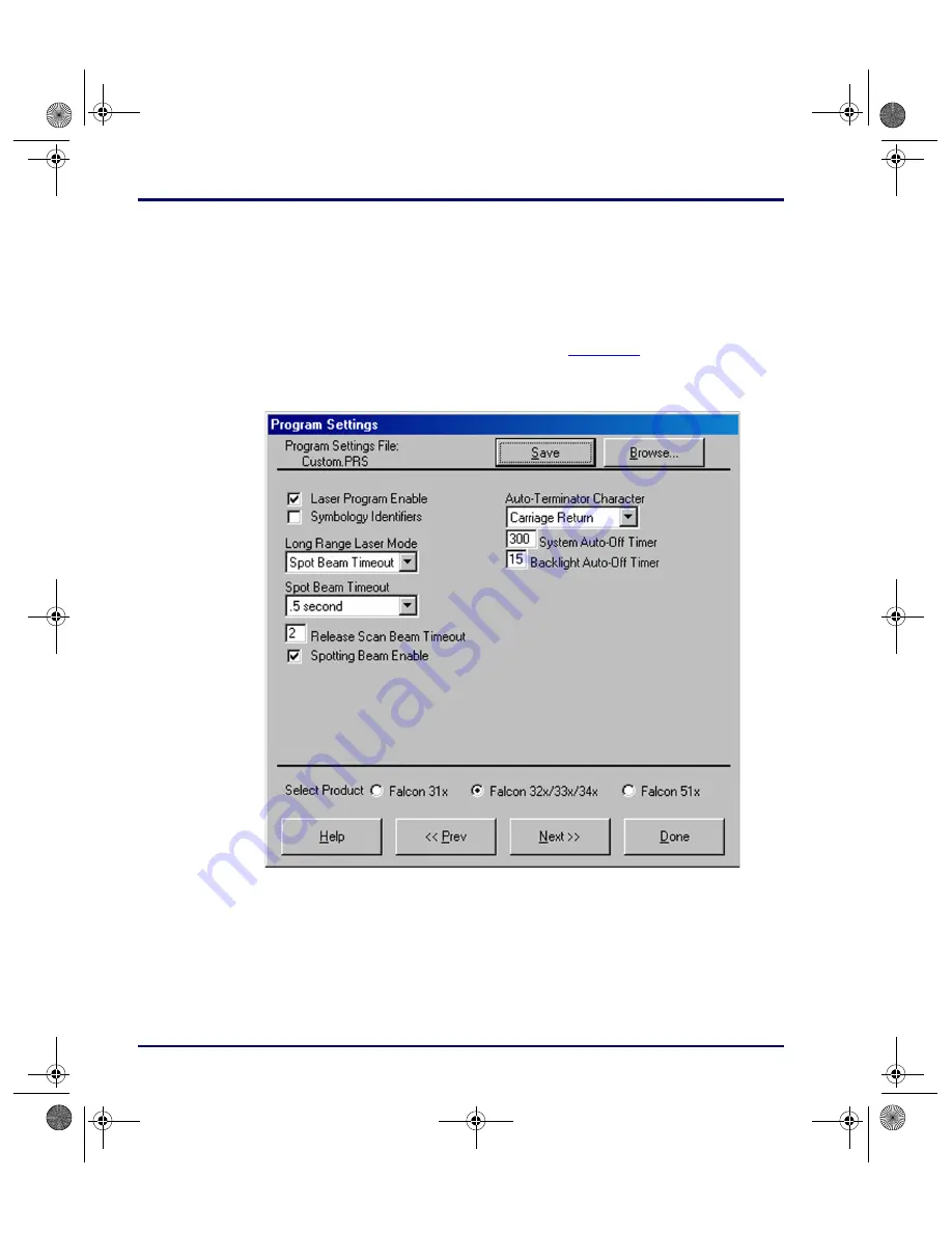
Figure 2-14: The Sixth Program Settings Window 

Program Settings File: 

This field shows the program-settings file that will be 

loaded into the Falcon.

Save

After selecting options in this window, select 

Save

 to save the revisions in the 

current program-settings file or in a new one.

Browse

1.

Select 

Browse

 to use a different program settings file. 

advuser.book  Page 18  Friday, September 27, 2002  4:22 PM

Summary of Contents for DOS Portable Data Terminals

Page 1: ...FALCON DOS Portable Data Terminals Advanced User s Guide 2278_fc fm Page i Monday October 7 2002 10 40 AM...

Page 2: ...4991692 5001406 5015831 5019697 5019698 5086879 5115120 5144118 5146463 5179270 5198649 5200597 5202784 5208449 5210397 5212371 5212372 5214270 5229590 5231293 5232185 5233169 5235168 5237161 5237162...

Page 3: ...ng Falcon DOS Portable Terminals 1 1 Overview 1 2 Programming the Laser Triggers 1 2 Programming the Enter Keys 1 3 Using PC Cards 1 4 Opening the PC Card Slot Cover 1 5 Inserting a PC Card 1 6 Card R...

Page 4: ...ransfer Tab 3 5 Logging Tab 3 7 Host Mode 3 8 Sending and Receiving Data 3 8 Send File to Portable 3 9 Receive File from Portable 3 9 Using XFER 3 10 Syntax and Parameters 3 11 The XFER_ARGS Environme...

Page 5: ...FGIO EXE 6 4 COMIO COM 6 5 DECODE SYS 6 6 FLASHDSK SYS 6 7 FORMAT COM 6 8 LOCK COM 6 9 ORGANIZE COM 6 10 PM COM 6 11 VDISK SYS 6 13 XFER EXE 6 14 Chapter 7 Resetting the Falcon 7 1 Overview 7 2 Warm B...

Page 6: ...ATTRIB B 6 BUFFERS B 7 CHKDSK B 8 COMMAND B 9 DELTREE B 11 DIR B 12 FCBS B 14 FIND B 15 HELP B 16 NEWFILE B 16 PRINT B 17 SHARE B 19 SWITCHES B 20 TREE B 20 VER B 21 XCOPY B 22 Appendix C Programming...

Page 7: ...D 2 Interleaved 2 of 5 D 3 ENABLE D 3 MINIMUM LENGTH D 3 MAXIMUM LENGTH D 3 ENABLE CHECKSUM D 3 SEND CHECKSUM D 3 USE LENGTHS 6 AND 14 ONLY case code D 3 Matrix 2 of 5 D 3 ENABLE D 3 MINIMUM LENGTH D...

Page 8: ...DIGIT S D 8 Code 128 D 8 ENABLE D 8 MINIMUM LENGTH D 9 MAXIMUM LENGTH D 9 Labelcode 4 5 D 9 ENABLE D 9 CONVERT D 9 UPC A Universal Product Code A D 9 ENABLE UPC A D 9 ENABLE UCC EAN 128 D 9 UPC E Univ...

Page 9: ...rtz D 12 NUMBER OF GOOD READ BEEPS D 12 GOOD READ BEEP DURATION D 12 BEEPER VOLUME D 12 ERROR BEEP TONE in Hertz D 13 LONG RANGE TRIGGER MODE D 13 SPOTTING BEAM ENABLE D 13 SPOT BEAM TIMEOUT in second...

Page 10: ...Contents viii Falcon DOS Portable Terminals NOTES advuser book Page viii Friday September 27 2002 4 22 PM...

Page 11: ...ONTENTS Overview viii Falcon Model Numbers viii Radio Frequency Interference x Style Conventions xi Document Conventions xi Keys and Keystroke Conventions xi Technical Support xii advuser book Page ix...

Page 12: ...terminals It is not intended for use by first time Falcon users Falcon Model Numbers Falcon DOS portable data terminals are handheld computers designed for data collection The product title Falcon re...

Page 13: ...y features in common with the Falcon 31X These models are often grouped together throughout this manual On the cover of this manual the Falcon 32X is represented by the Falcon 325 second from the uppe...

Page 14: ...nada This equipment has been tested and found to comply with the limits for a Class A digital device pursuant to Part 15 of the FCC Rules These limits are designed to provide reasonable protection aga...

Page 15: ...lics text This text appears in gold bold italics text if the user is viewing the manual in electronic PDF form on their computer Warnings Warnings appear when there is something of extreme importance...

Page 16: ...information is an authorized PSC reseller A reseller is directly acquainted with specific types of businesses application software and computer systems and therefore is in the best position to provide...

Page 17: ...1 3 Using PC Cards 1 4 Opening the PC Card Slot Cover 1 5 Inserting a PC Card 1 6 Card Recognition and Configuration 1 7 Removing a PC Card 1 8 The Serial Port 1 8 The IR Serial Port 1 8 The Disk Dri...

Page 18: ...of the laser triggers can be reprogrammed to act as equivalents of keypad keys To turn a trigger into an alias for a keypad key 1 Hold down the FN 1 and FN 2 keys 2 Press the SWAP key and the program...

Page 19: ...mode 2 Press the trigger twice Programming the Enter Keys Falcon 33x and 34x models allow reprogramming of one of the Enter keys One Enter key may be reprogrammed from a list of available keys There...

Page 20: ...d wireless capability Their primary purpose in the Falcon is to provide additional memory storage by functioning as a disk drive See page page 1 9 for information about the Falcon s drives Press the A...

Page 21: ...ed by a screw loosen the screw Then while pressing the round button above the slot cover slide the cover out and away from the Falcon Figure 1 2 Removing the PC Card Slot Cover on a Falcon 310 1 Remov...

Page 22: ...PC Card To insert a PC card into a Falcon complete the following steps 1 Start with the Falcon face down and the PC card face up 2 Insert the end of the card with the sockets into the card slot refer...

Page 23: ...may be disabled Do not force the card into the slot It should slide in easily Ejector tab The PC card slot on the Falcon is designed so a card cannot be inserted upside down or backward If the card d...

Page 24: ...it is a 10 pin telephone style jack providing a standard RS 232 connection With a serial cable connected to it the port allows communications with a host computer or any serial device such as a print...

Page 25: ...RTS CTS DTR DSR RI and DCD Figure 1 6 The IR Serial Port on the Falcon 33x and 34x The Disk Drives The Falcon contains four logical disk drives that provide storage for system files applications and d...

Page 26: ...12 or directly in CONFIG SYS refer to page 6 13 The Falcon may also be configured to use PC ATA flash cards The PC Card is identified as a hard disk drive by the operating system This drive may be us...

Page 27: ...hanged XFER can be run from any drive on the Falcon However before running XFER32 on a PC install the Falcon Configuration Utility onto the hard drive By default XFER32xfer32 is placed in the director...

Page 28: ...port to use Replace the symbol with the desired setting 1 COM1 2 COM2 1 B Specifies the baud rate Replace the symbol with the desired setting 2400 4800 9600 19200 38400 57600 115200 19200 D Specifies...

Page 29: ...Configuration Utility 2 3 Main Menu 2 3 The Custom Configuration Menu 2 5 The File Configuration Windows 2 9 The Program Settings Windows 2 16 The Comm Settings Dialog Box 2 20 The File Transfer Windo...

Page 30: ...n If the autoplay does not come up access the CD using Windows Explorer Go to the install directory and run setup exe 3 At the autoplay menu select the Falcon Configuration utility 4 Copy the file to...

Page 31: ...t this option to load the original factory configuration into the Falcon unit The Configuration utility prepares files to be transferred to the Falcon and opens the Important dialog box Figure 2 2 2 C...

Page 32: ...be loaded into the Falcon unit See the next section for information on the Custom Configuration menu Comm Settings Select this option to modify settings for the computer s serial port Refer to page 2...

Page 33: ...34x or 51x The Custom Configuration Menu 1 Select Custom from the main menu 2 An Open dialog box appears refer to Figure 2 3 on page 2 6 3 Use this dialog box to select a configuration file from the...

Page 34: ...ettings file is loaded the Custom Configuration menu appears Figure 2 4 on page 2 7 File Configuration Select this option to choose application files to be loaded into the Falcon Refer to page 2 9 thr...

Page 35: ...at will be used Select the check box to load the program settings Deselect it to turn this option off Comm Settings Select this option to view or change serial communications settings for the Falcon S...

Page 36: ...nu If changes were made to the file configuration or program settings one or both of the following prompts appear Figure 2 5 The Prompt for Saving Changes to the Current File Configuration Figure 2 6...

Page 37: ...ndows to choose application files to be loaded into the Falcon Configuration File This field shows the configuration file used to specify the files that will be loaded into the Falcon Save After addin...

Page 38: ...iles associated with the main application Add Select this option to include other files to be installed on the Falcon unit The File Selection dialog box opens Enter path and filename on host PC Use th...

Page 39: ...select Edit to change the source path or destination path for the file The Edit File Properties dialog box opens Figure 2 9 The Edit File Properties Dialog Box for an Application File Delete To delet...

Page 40: ...uration window Figure 2 10 appears if Next is selected in the first window Figure 2 10 The Second File Configuration Window Configuration File This field shows the configuration file used to specify t...

Page 41: ...n this switch on to transfer drivers for other types of PC cards This option loads PC Card drivers for Card and Socket Services only Generic client drivers such as ATA or I O Card drivers are not load...

Page 42: ...ne to return to the File Configuration window Select Product Select the appropriate radio button for type the Falcon model being configured 31x 32x 33x 34x or 51x Prev Select Prev to return to the pre...

Page 43: ...ws the configuration file used to specify the files that will be loaded into the Falcon Save After selecting options in this window select Save to save the revisions in the current configuration file...

Page 44: ...Select Prev to return to the previous file configuration window Done Select Done when finished setting file configuration options for the custom installation The Program Settings Windows 1 Select the...

Page 45: ...the changes are not saved the prompt shown in Figure 2 6 on page 2 8 appears On Off Switches The smaller white boxes are on off switches Click in the box to toggle a switch Input Fields Enter specifi...

Page 46: ...e sixth Program Settings window Figure 2 14 appears if Next is selected in the fifth window Figure 2 14 The Sixth Program Settings Window Program Settings File This field shows the program settings fi...

Page 47: ...after making changes in this or any other File Configuration window and the changes are not saved the prompt shown in Figure 2 6 on page 2 8 appears Spotting Beam Enable Select to enable the Spotting...

Page 48: ...Falcon DOS Portable Terminals User s Guide on page 38 Drop Down Lists Click on the list to view the options and select the desired option Radio Buttons Select the desired setting by clicking on it Pre...

Page 49: ...the File Transfer window appears Figure 2 18 on page 2 22 2 Use this window to select data files for transfer between the Falcon and the computer List File This field shows the name of the file list...

Page 50: ...tion file from the Filelist folder 4 If Browse is selected after making changes in this or any other File Transfer window and the changes are not saved the following prompt appears Figure 2 18 The Pro...

Page 51: ...2 19 on page 2 23 Figure 2 19 The File Selection Dialog Box for Adding a Data File Enter path and filename on host PC Use this field to specify the location of the file on the PC Enter path and filen...

Page 52: ...pens the Important dialog box Figure 2 2 on page 2 5 2 Make certain the Falcon unit is properly connected to the serial port specified in the Comm Settings dialog box refer to page 2 20 3 Then run the...

Page 53: ...ng Data 3 8 Send File to Portable 3 9 Receive File from Portable 3 9 Using XFER 3 10 Syntax and Parameters 3 11 The XFER_ARGS Environment Variable 3 26 Multiple Option Blocks 3 27 The Modem Initializa...

Page 54: ...FER32 User Interface XFER32 Setup To prepare for data transfer between the PC and the PT40 click on the Setup button to open the Setup dialog box which contains three tabbed sections The settings in t...

Page 55: ...ition Form General Tab Connection Enter the Connection port for file transfers Select from the list of detected serial ports or modems Baud Rate Select a Baud Rate for serial communications from the p...

Page 56: ...s Flow Control Select the mechanism used to control the flow of data Sender and receiver must agree on the flow control method None No flow control used XON XOFF Software flow control using XON and XO...

Page 57: ...ender Follows the sender s Crash Recovery and Overwrite options Always Forces an attempt to recover from a file transfer Sender Timeout Seconds Enter the maximum number of seconds to wait for a connec...

Page 58: ...received file already exists Source Longer or Newer Overwrites the existing file if the received file is longer or newer CRCs Don t Match Overwrites the existing file if the CRCs of both files don t...

Page 59: ...s displayed on screen Append to Log This option becomes available when you select Log to File When enabled Append to Log adds log information to the end of the log file If not enabled new log informat...

Page 60: ...he portable dock documentation for more information UPG uses the File Transfer Manager to transfer data collection validation and INI files between a portable data collection unit and the host PC It i...

Page 61: ...incoming file 1 Select Transfer Files Receive from the menubar If the Path Filename Transmission is set to Specify Receiver s File Pathname the file names may be altered prior to being sent to the re...

Page 62: ...me s supplied by the sender Press Cancel to select this option 3 Click Open to begin receiving the file z Press Cancel to not receive any files Using XFER XFER xfer exe is a DOS utility that directs t...

Page 63: ...ommand line Basic options and their defaults are listed and described in Table 3 1 The Default column indicates whether the option is used On or ignored Off if it is not included in the command line F...

Page 64: ...om the beginning of the file 2 Follow sender use the sender s crash recovery options ignore the receiver s 3 Always recover send data from the point where transmission was interrupted N A 1 D page 3 1...

Page 65: ...nger or newer Zmodem only 2 Overwrite if CRCs don t match Zmodem only 3 Append to existing file Zmodem only 4 Always overwrite 5 Overwrite if source is newer Zmodem only 6 Overwrite if dates or length...

Page 66: ...n t exist on a receive the transfer will fail with a file open error DOS accepts only 128 characters on the command line but a response file can be used to get around this limitation Refer to the file...

Page 67: ...llows circumvention of the DOS limitation of 128 characters on the command line when sending many files in a single transfer session When using a response file fill the file with the filenames to be s...

Page 68: ...es the baud rate to be used for the file transfer Replace the symbol with the desired setting 2400 4800 9600 19200 38400 57600 115200 C Crash Recovery Zmodem only Crash recovery refers to the ability...

Page 69: ...options Any overwrite options local to the receiver will be ignored This is useful if a default crash recovery command is specified in the XFER_ARGS environment variable refer to page 3 26 and crash...

Page 70: ...ransfer of data XFER supports two types of flow control software XON XOFF and hardware RTS CTS Only one type can be used at a time The sender and receiver should have this option enabled similarly To...

Page 71: ...ief description of the XFER syntax options and settings Ifile Modem Initialization File This option specifies the file that contains modem setup and control commands Refer to The Modem Initialization...

Page 72: ...ied in the XFER_ARGS environment variable refer to page 3 26 but are transferring files without a modem for the current transfer session N Ignore Previous Option Settings This option causes XFER to ig...

Page 73: ...date or time of a received file to match the original date or time of the sender s version of the file Instead the date and time are taken from the receiver s operating system when the file is receiv...

Page 74: ...n the command line inverts the quiet mode state By default XFER has quiet mode off The first occurrence of the Q option turns quiet mode on the next turns it back off and so on This is most useful if...

Page 75: ...ified with a filename before sending the filename to the receiver The new filename will be transmitted to the receiver without any path information The file will be stored by the receiver in the curre...

Page 76: ...ng with the drive and the path Correct examples Incorrect examples In the second incorrect example the additional spaces would be included in the receiver s filename This is generally wrong but it may...

Page 77: ...edgment to Zmodem protocol With windowing the sender will send up to the number of bytes specified by the size of the window and then stop transmitting data until the receiver acknowledges that it has...

Page 78: ...riable can be used to set option settings for most transfer sessions Even files can be specified in the XFER_ARGS environment variable Parsing of the XFER command line starts with the XFER_ARGS variab...

Page 79: ...in the XFER command line Xmodem protocol is specified The only overwrite settings that Xmodem supports are O4 always overwrite and O7 never overwrite all other O options resolve to O7 for Xmodem If t...

Page 80: ...ce modem command syntax errors Correct examples The first two command lines above are valid because the b115200 setting is always at the end of the multiple option block Also in the second example the...

Page 81: ...in a line are ignored for that line Keywords ACCESS_DELAY This keyword specifies the number of milliseconds for XFER to wait for a response from the local modem when sending a command to the local mo...

Page 82: ...However the combined length of all the values assigned to FAIL_STRING cannot exceed 115 characters HANDSHAKING This keyword controls the type of handshaking the Falcon will perform with the modem Gen...

Page 83: ...dem to dial Up to ten phone numbers may be specified with each one assigned a keyword NUMBER0 through NUMBER9 Any number may be assigned to a keyword unless the number has already been assigned It is...

Page 84: ...s for the receiver to write data to the disk To avoid this problem use Zmodem with either windowing refer to page 3 25 or flow control refer to page 3 18 INIT_STRING ATE1Q0V1X4 C1 D2S7 10s9 6s10 20S11...

Page 85: ...nctions Because Card and Socket Services chain into this interrupt and execute some code with interrupts disabled the system may become overburdened when running serial interrupts at high speed greate...

Page 86: ...ABORT_FTPERROR An invalid file transfer protocol option was selected 7 ABORT_CHECKERROR A checksum or CRC error occurred 8 ABORT_MEMORYERROR An error occurred while trying to allocate memory from the...

Page 87: ...con 4 Slot Dock CHAPTER CONTENTS Overview 4 2 Operating Modes 4 2 The 4SLOT SYS Device Driver 4 3 Transferring Files with XFER 4 4 Setting the Baud Rate 4 5 advuser book Page 1 Friday September 27 200...

Page 88: ...fault the Falcon 4 Slot Dock network grants access to the communications line to individual portables on a priority basis z In host controlled mode the host controls which portable gets access to the...

Page 89: ...tion Utility can transfer the 4slot sys driver to the portable and modify the config sys file Complete the following steps 1 Install the Developer s Toolkit software on the computer Follow the install...

Page 90: ...the XFER command is executed on the host XFER will transfer the file from the host to the portable When XFER exits on the portable the COM LED goes out indicating that the portable has relinquished a...

Page 91: ...oaded if the host is to control that portable Complete the following steps 1 Set the host communications package or program to 2400 baud Send a single space to the dock network There will not be any f...

Page 92: ...it out the COM port from an application or copying it to the COM port device driver under DOS For complete information about sending commands to a Falcon 4 Slot Dock see the Falcon DOS Portable Data T...

Page 93: ...tructure 5 2 Drive A 5 3 Drive B 5 4 Drive C 5 6 Drive D 5 6 Additional Drives 5 7 Other System Software 5 7 BIOS and DOS 5 7 PC Card and RF Networking Software 5 8 System Configurations 5 8 Default C...

Page 94: ...not require updating of this drive Drive C is a resident flash disk drive that is accessed with the flashdsk sys device driver Use this drive to store applications and data Drive D is a RAM disk acce...

Page 95: ...he unit needs to run correctly refer to Figure 5 1 and Figure 5 2 Both files chain to their respective counterparts on the B drive as described in the next section Figure 5 1 Config sys File on Drive...

Page 96: ...s the second file in the boot sequence z coreupd com the utility that updates the firmware image z decode sys the bar code decoding device driver page 6 6 z flashdsk sys the resident flash disk device...

Page 97: ...RAM drives When the safe boot sequence is initiated refer to page page 7 4 the config saf file is processed instead of the config sys file This prevents chaining into the drive C initialization files...

Page 98: ...he C drive and the proper entries will be transferred into the config sys and autoexec bat files The exact configuration of files and the contents of the config sys and autoexec bat files will change...

Page 99: ...ed for this it will appear as Drive E The Falcon can be configured to use an ATA flash card The PC card looks like a hard disk drive to the operating system and the user More flexible than flash disk...

Page 100: ...t is to be supported Two standard configurations are described below along with directory structures and default config sys and autoexec bat file descriptions Default Configuration The configuration c...

Page 101: ...Card Support REM REM The following lines set up default parameters for some REM environment variables These lines may be modified or REM overridden in the USER section below REM set prompt p g set dir...

Page 102: ...verridden in the USER section below REM set prompt p g set dircmd ogn p REM REM The following section is for customized user entries REM REM REM Insert user specific options and commands here REM REM...

Page 103: ...Chapter Conventions 6 2 CFGDEV SYS 6 2 CFGIO EXE 6 3 COMIO COM 6 3 DECODE SYS 6 4 FLASHDSK SYS 6 5 FORMAT COM 6 5 LOCK COM 6 5 ORGANIZE COM 6 6 PM COM 6 7 VDISK SYS 6 8 XFER EXE 6 8 advuser book Page...

Page 104: ...code labels beginning with and ending with EE can be scanned using any bar code scanning device Appendix D contains many useful labels z File Copy Files containing the bar code programming strings ca...

Page 105: ...ies the name of the file containing the new font set to be loaded into the system Font files have the extension fnt keymap Specifies the name of the file containing the new keypad map to be loaded int...

Page 106: ...her one may be changed independently Syntax COMIO b h k v b Specifies the baud rate to use If not specified the current baud rate is used h Displays a help file for the utility k Changes keyboard redi...

Page 107: ...ored on it This provides a quick method for cleaning out an existing drive Syntax FORMAT drive y Options drive Specifies the letter of the drive to be formatted If a drive letter is not specified the...

Page 108: ...ors are grouped together reducing the overhead of freeing space for new data Organize com has a greater effect on a flash disk as the disk gets closer to being full Syntax ORGANIZE drive y Options dri...

Page 109: ...the number of minutes between soundings of the tone The tone will not sound until the battery has been in the low state for the same number of minutes The range of acceptable values for is 0 off to 2...

Page 110: ...entries Options disk_size Specifies the size of the RAM disk in kilobytes The default disk size is 64 KB If the amount of available Extended Memory is less than the disk size specified here the size o...

Page 111: ...7 Resetting the Falcon CHAPTER CONTENTS Overview 7 2 Warm Boot 7 2 Cold Boot 7 3 Safe Boot 7 4 Hardware Reset 7 5 reset fm Page 1 Monday October 7 2002 10 28 AM...

Page 112: ...rm Boot Key Sequences Since a warm boot can be attempted only from a unit that has been turned on certain assumptions are made For example the rigorous hardware tests that are performed as part of the...

Page 113: ...on to this is when the backup battery is drained of all power a condition that should never be allowed to happen When a cold boot is performed all transient data is lost along with the state of any ap...

Page 114: ...utoexec bat file on drive C and the loading of the cfgdev sys and decode sys drivers can be taken out of the normal boot sequence DOS can help some with the CTL C and F8 escape sequences Table 7 3 Fal...

Page 115: ...two keys simultaneously immediately upon seeing the Wait message on the display Attempt at least two cold boots before going into Hardware reset Refer to page 7 3 for instructions on performing a col...

Page 116: ...he Falcon 7 6 Falcon DOS Portable Terminals Hardware Reset Mechanism on Falcon 31x and 32x Figure 7 1 Hardware Reset Mechanism for the Falcon 33x 34x 38 key keypad reset fm Page 6 Monday October 7 200...

Page 117: ...8 Using PC Cards CHAPTER CONTENTS Overview 8 2 Uses of PC Cards 8 2 PC Card Drivers 8 3 advuser book Page 1 Friday September 27 2002 4 22 PM...

Page 118: ...imary intended uses for PC cards with the Falcon are expanded storage space and radio frequency RF communications ATA flash memory cards can be added to increase memory The card appears as a hard driv...

Page 119: ...will be necessary Many LAN cards come with their own resource management system and do not require the pcmscd exe driver RF Cards Because of the special requirements of RF environments PSC is distribu...

Page 120: ...ards z pcmcs exe is the card services driver Required for all PC cards it provides an interface between applications and the socket services It also manages resource allocations for the PC cards z pcm...

Page 121: ...con Portable Terminals A 2 Laser Scanner Connector A 2 Serial Port Jack A 3 Serial IR Port A 4 Falcon Dock A 5 25 Pin Connector A 5 Falcon 4 Slot Dock A 6 Host Interface Cable A 7 Dock Network Cable J...

Page 122: ...on 4 Slot Dock Falcon Portable Terminals Some Falcon models 31x and 32x have a standard 9 pin connector for scanner input at the top and a 10 pin telephone style jack in the serial port at the bottom...

Page 123: ...3 Good read out 4 Scan enable out Not normally used 5 Laser trigger in 6 Laser scan enable out 7 GND 8 GND 9 5V out 300mA max Pin Signal Notes Pin 10 Pin 1 Pin Signal Notes 1 DCD in RS 232 2 5V out 3...

Page 124: ...d Docking Pads on the Falcon 33x and 34x In addition there are three pads along the bottom of the unit These three pads are used when the Falcon is in the dock Hold the Falcon oriented with its keypad...

Page 125: ...Falcon Dock 25 Pin Connector Figure A 5 shows the a 25 pin dock to host cable connector on the back of the Falcon dock Figure A 5 25 Pin Cable Connector on the Falcon Dock Table A 3 Pinouts for Falco...

Page 126: ...ions The upstream side is the side closer to the host the downstream side is farther from the host Figure A 6 Back Panel of the Falcon 4 Slot Dock Pin Signal 1 Frame GND 2 Portable TXD 3 Portable RXD...

Page 127: ...ost Interface Cable Dock Network Cable Jacks The wiring for the dock network cable jacks are shown in Table A 6 The network signals are differential type and are routed on twisted pair wiring The pino...

Page 128: ...ownstream Connector 1 Vcc Not used 2 HostXmtIn HostXmtOut 3 HostXmtIn HostXmtOut 4 ReqOut ReqIn 5 HostRcvOut HostRcvIn 6 HostRcvOut HostRcvIn 7 ReqOut ReqIn 8 InhIn InhOut 9 InhIn InhOut 10 GND Not us...

Page 129: ...Descriptions B 5 ATTRIB B 6 BUFFERS B 7 CHKDSK B 7 COMMAND B 9 DELTREE B 11 DIR B 12 FCBS B 14 FIND B 14 HELP B 15 NEWFILE B 16 PRINT B 17 SHARE B 18 SWITCHES B 19 TREE B 20 VER B 21 XCOPY B 21 B ROM...

Page 130: ...stop program execution at a non I O point BUFFERS A config sys command Sets the number of internal data buffers CALL Batch subcommand Invokes execution of a secondary batch file CHDIR CHange DIRector...

Page 131: ...the maximum number of drives MENUDEFA ULT Sets the default menu item choice and time out value for making a selection MENUITEM Specifies an item to be placed in the startup menu displayed during syste...

Page 132: ...of each directory on a specified drive TYPE Displays the contents of a text file on the viewport VER Displays current version of ROM DOS on the viewport VERIFY Displays the current VERIFY state or set...

Page 133: ...tes O C and O C Sorts by compression ratio C H Displays compression ratio of files compressed using Drivespace or Doublespace FCBS minimum number FIND I Not case sensitive HELP Requires command hlp MS...

Page 134: ...ibutes Wildcard characters may be used in the ATTRIB filespec The ATTRIB command will modify file attributes if modify commands are given to ATTRIB The modify commands are If no modify commands are fo...

Page 135: ...m The minimum number of buffers is 2 and the maximum number is 40 If a number less than 2 is given then the number of BUFFERS is set to 2 If a number larger than 40 is given then BUFFERS is set to 40...

Page 136: ...ll not be saved to the disk The C option allows CHKDSK to correct errors without user confirmation This option must be used along with the F option for corrections to be made The V option causes CHKDS...

Page 137: ...that has all the internal DOS commands in it Starting a new command processor will also produce a new environment The size of the environment is 128 bytes by default but it can be changed using the E...

Page 138: ...keeps many of its error messages in the resident part of COMMAND COM rather than using valuable memory to store them If an error message is needed and ROM DOS has been loaded from a diskette the mess...

Page 139: ...are allowed Options The Y switch prevents DELTREE from prompting before deleting Examples The following DELTREE command deletes all files and directories in the tree C TEMP DELTREE C TEMP Use DELTREE...

Page 140: ...lespec and have the given attribute The table below shows the legal attribute descriptions The dash symbol can be used to negate listed attributes For example to select all files that do not have the...

Page 141: ...l assign the values to an environment variable Refer to the SET command section for proper usage For example to always have the P option set for DIR the statement SET DIRCMD P could be used The defaul...

Page 142: ...fault for this value is 4 The value for number must be in the range from 1 to 255 The minimum number specifies the minimum number of FCBs to be open at all times The minimum number argument has the sa...

Page 143: ...e drive and path can be specified Wildcard characters can be used in the filename Examples The following example shows each line in the file JUNK C that contains the string printf FIND printf junk c T...

Page 144: ...n another directory or even on a different drive Syntax NEWFILE filename Remarks The NEWFILE command is especially useful when the CONFIG SYS file is located on an inaccessible drive or in ROM Additio...

Page 145: ...NEWCFG SYS located in the C BIN directory to be executed as part of the CONFIG SYS file The contents of NEWCFG SYS may include any of the commands listed in this section NEWFILE C BIN NEWCFG SYS PRIN...

Page 146: ...y allowed the first time PRINT is run or until the next system reboot The P option causes all files listed after this option to be submitted for printing This is the default for filenames encountered...

Page 147: ...of files that can be locked at one time The default number of files is 20 The U option unloads the share utility and frees the memory SHARE will not unload if other TSRs have been loaded on top of it...

Page 148: ...g the F5 and F8 keys at boot time switches n TREE Type External Purpose The TREE command displays each subdirectory and optionally the files within them for a specified drive Syntax TREE drive F Remar...

Page 149: ...full version and release number of ROM DOS Example The following example changes the record of current DOS version in use to DOS 5 0 Any programs that are executed following this command will recogni...

Page 150: ...those source files that have the archive bit set Once the source file is copied the archive bit is reset The P option causes XCOPY to prompt before each file is copied The prompt appears as follows C...

Page 151: ...3 Code 11 B 4 Codabar Ames B 4 MSI B 4 Code 93 B 4 Universal Product Code A UPC A B 4 Universal Product Code E UPC E B 5 European Article Numbering EAN Japan Article Numbering JAN B 5 UPC EAN JAN Exte...

Page 152: ...r each good read z Acceptable Input gives the settings or range of settings for each code parameter z Defaults tells how the parameter is set when the predefined default D0 D1 or D2 is selected z Pred...

Page 153: ...m 0B On Off On or Off Off Off Off Send checksum 0C On Off On or Off Off Off Off Use lengths 6 and 14 only case code 0D On Off On or Off Off Off Off Matrix 2 of 5 Enter 1 for On and 0 for Off Enable 10...

Page 154: ...owed 25 On Off On or Off Off Off On MSI Enter 1 for On and 0 for Off Enable 26 On Off On or Off Off On Off Minimum length 27 Value 01 14 01 01 04 Maximum length 28 Value 01 14 01 14 10 Require 2 check...

Page 155: ...for Off Allow 2 digit extensions 3C On Off On or Off Off On On Allow 5 digit extensions 3D On Off On or Off Off On On Require extensions 3E On Off On or Off Off Off Off Code 128 Enter 1 for On and 0...

Page 156: ...beeps B9 Value 01 04 01 01 01 Good read beep duration BA Value 00 0 07 sec 01 0 13 sec 02 0 18 sec 03 0 36 sec 00 00 00 Beeper volume BC Value 00 Off 01 09 01 Lowest 07 Highest 08 Higher 09 Lower 07 0...

Page 157: ...EL reboot E0 On Off On or Off Off Off On Enable trigger programmability Note that for the Falcon 33x this will effect Enter key programmability E1 On Off On or Off On On On Backlight auto off timeout...

Page 158: ...Programming Parameters C 8 Falcon DOS Portable Terminals NOTES advuser book Page 8 Friday September 27 2002 4 22 PM...

Page 159: ...ram the Falcon refer to Chapter 2 APPENDIX CONTENTS Predefined Defaults D 2 Code 39 D 2 Interleaved 2 of 5 D 3 Matrix 2 of 5 D 3 Standard 2 of 5 D 4 Code 11 D 5 Codabar Ames D 6 MSI D 7 Code 93 D 8 Co...

Page 160: ...E 0 1 0 0 E E 0 1 1 0 E E 0 1 2 0 E E 0 1 3 0 E E 0 1 4 0 E E 0 1 5 0 E E MAXIMUM LENGTH 1 10 20 30 40 50 ENABLE CHECKSUM On Off SEND CHECKSUM On Off FULL ASCII MODE On Off 0 2 0 1 E E 0 2 1 0 E E 0 2...

Page 161: ...E E 0 9 0 6 E E 0 9 1 0 E E 0 9 2 0 E E 0 9 3 0 E E 0 9 4 0 E E 0 9 5 0 E E 0 A 0 2 E E 0 A 1 0 E E 0 A 2 0 E E 30 40 50 ENABLE CHECKSUM On Off SEND CHECKSUM On Off USE LENGTHS 6 AND 14 ONLY case code...

Page 162: ...1 0 6 E E 1 1 2 0 E E 1 1 3 0 E E 1 1 4 0 E E 1 1 5 0 E E 1 2 0 1 E E 1 2 1 0 E E 1 2 2 0 E E 1 2 3 0 E E 1 2 4 0 E E 50 ENABLE CHECKSUM On Off SEND CHECKSUM On Off ENABLE On Off MINIMUM LENGTH 1 6 1...

Page 163: ...6 5 0 E E 1 7 0 1 E E 1 7 1 0 E E 1 7 2 0 E E 1 7 3 0 E E 1 7 4 0 E E 1 7 5 0 E E 1 8 1 E E 1 8 0 E E 1 9 1 E E Off USE 2 BAR START STOP On Off ENABLE On Off MINIMUM LENGTH 4 10 20 30 40 50 1 9 0 E E...

Page 164: ...E 1 D 2 0 E E 1 D 3 0 E E 1 D 4 0 E E 1 D 5 0 E E 1 E 1 E E 1 E 0 E E 1 F 1 E E 1 F 0 E E 2 0 1 E E Off AMES ENABLE On Off MINIMUM LENGTH 1 4 10 20 30 40 50 MAXIMUM LENGTH 1 10 20 2 0 0 E E 5 1 1 E E...

Page 165: ...2 4 0 E E 2 2 5 0 E E 2 3 1 E E 2 3 0 E E 2 4 1 E E 2 4 0 E E 2 5 1 E E 2 5 0 E E 2 6 1 E E Off MINIMUM LENGTH 1 4 7 10 12 14 MAXIMUM LENGTH 1 4 7 10 12 14 2 6 0 E E 2 7 0 1 E E 2 7 0 4 E E 2 7 0 7 E...

Page 166: ...LENGTH 2 10 2 9 1 E E 2 9 0 E E 2 A 1 E E 2 A 0 E E 2 B 1 E E 2 B 0 E E 2 C 1 E E 2 C 0 E E 2 D 0 2 E E 2 D 1 0 E E 20 30 40 50 MAXIMUM LENGTH 2 10 20 30 40 50 ENABLE On Off 2 D 2 0 E E 2 D 3 0 E E 2...

Page 167: ...0 1 E E 4 1 0 2 E E 4 1 1 0 E E 4 1 2 0 E E 4 1 3 0 E E 4 1 4 0 E E 4 1 5 0 E E 4 2 0 1 E E 4 2 1 0 E E 4 2 2 0 E E 4 2 3 0 E E 4 2 4 0 E E 4 2 5 0 E E On Off ENABLE On Off CONVERT On Off ENABLE UPC...

Page 168: ...0 On Off USE SYSTEM DIGIT 1 On Off CONVERT UPC E TO UPC A On 3 1 0 E E 3 2 1 E E 3 2 0 E E 3 3 1 E E 3 3 0 E E 3 4 1 E E 3 4 0 E E 3 5 1 E E 3 5 0 E E 3 6 1 E E Off SEND SYSTEM DIGIT On Off SEND CHECK...

Page 169: ...IONS On Off 3 B 1 E E 3 B 0 E E 3 F 1 E E 3 F 0 E E 3 C 1 E E 3 C 0 E E 3 D 1 E E 3 D 0 E E 3 E 1 E E 3 E 0 E E AUTOTERMINATOR CR TAB None AUTO OFF TIMER Off 20 sec 40 sec 1 min 2 min 3 min 4 min 5 mi...

Page 170: ...8 0 2 E E B 8 0 4 E E B 8 0 6 E E B 9 0 1 E E B 9 0 2 E E B 9 0 3 E E B 9 0 4 E E B A 0 0 E E B A 0 1 E E 0 18 0 36 BEEPER VOLUME Off Lowest Medium Highest Higher Lower ERROR BEEP TONE in Hertz 2580...

Page 171: ...1 E E D 7 0 E E D 5 0 0 E E D 5 0 1 E E D 5 0 2 E E D 5 0 3 E E D 5 0 4 E E D 6 0 1 E E D 6 0 2 E E D 6 0 3 E E 5 10 30 KEYPRESS SOUND Off Click Beep ENABLE CTL ALT DEL REBOOT On Off ENABLE TRIGGER P...

Page 172: ...2 0 7 E E E 2 0 9 E E E 2 1 5 E E E 2 2 0 E E E 2 3 0 E E E 3 0 1 E E E 3 0 2 E E DOUBLE KEY ACTION TIMEOUT delay in ms 165 220 275 330 385 440 495 550 605 660 E 4 0 0 E E E 4 0 1 E E E 4 0 2 E E E 4...

Page 173: ...ff timer bar codes for D 11 to D 12 settings for C 5 autoterminator bar codes for D 11 settings for C 5 B backlight timeout bar codes for D 14 settings for C 7 bar codes for programming D 1 to D 11 ba...

Page 174: ...erial port 1 8 communications serial port 1 8 selecting with configuration utility 2 21 COMPRESSION_STRINGS keyword 3 29 computer transferring files to and from 1 11 see also XFER config saf 5 3 on dr...

Page 175: ...Falcon Configuration Utility 2 13 transferring files in 1 11 version 5 7 DOS B 2 DOS commands B 1 to B 23 B 2 B 2 B 2 ATTRIB B 2 B 4 B 6 BREAK B 2 BUFFERS B 2 B 4 B 7 CALL B 2 CHDIR B 2 CHKDSK 5 6 B...

Page 176: ...settings for C 5 bar codes for programming D 1 to D 11 booting 7 1 to 7 6 communications port 1 8 configuring 1 10 2 1 to 2 21 connector configurations A 1 to A 8 disk drives 1 9 to 1 10 5 1 to 5 10...

Page 177: ...in Falcon Configuration Utility 2 21 to 2 24 filenames XFER 3 12 3 14 to 3 15 FILES B 3 files system 5 1 to 5 10 also see individual file names file transfer protocol 3 14 3 26 FIND B 3 B 5 B 15 flash...

Page 178: ...ar codes for D 9 settings for C 5 LAN cards 8 3 laser connector configuration A 2 long range bar codes for D 13 settings for C 6 to C 7 LASTDRIVE B 3 ld bat 5 4 using 2 3 2 8 2 24 local area network L...

Page 179: ...d from 1 11 pcm ini 8 4 pcmata sys 8 4 PCMCIA cards see PC cards pcmcs exe 8 4 pcmcsd exe 8 4 pcmscd exe 8 4 pcmss exe 8 4 Percon Portable Applications Library PAL 5 8 performance issues XFER 3 32 pin...

Page 180: ...B 4 Standard 2 of 5 bar codes for D 4 to D 5 settings for C 3 starting the Falcon Configuration Utility 2 2 streaming XFER 3 14 3 25 SUBMENU B 4 SWITCHES B 4 B 5 B 20 symbology identifier option bar c...

Page 181: ...ing to UPC A C 5 settings for C 5 utilities system see system utilities V variables environment DIRCMD B 13 XFER_ARGS 3 26 to 3 27 vdisk sys 5 2 5 4 5 5 6 13 VER B 4 B 5 B 21 VERIFY B 4 version DOS 5...

Page 182: ...xxiv Falcon DOS Portable Terminals advuser book Page xxiv Friday September 27 2002 4 22 PM...

Page 183: ...ctives and Standards Directives EMC 89 336 EEC Low Voltage 73 23 EEC R TTE 1999 5 EC Standards Equipment EN 55022 A B 1994 1998 EN 50082 1 1992 1998 EN 55024 1998 EN 60825 1 1996 EN60950 1998 Power Su...

Page 184: ...1 93 58 58 Italy PSC S p A Vimercate MI Italy Telephone 39 0 39 62903 1 Fax 39 0 39 6859496 Japan PSC Japan K K Shinagawa ku Tokyo Japan Telephone 81 0 3 3491 6761 Fax 81 0 3 3491 6656 Latin America P...

Reviews: