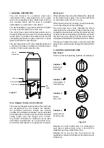
Vent to
atmosphere
Drip cock
Spark igniter
Drain cock
Gas
control
1. GENERAL DESCRIPTION
The unit consists of a stainless steel oven
compartment with a side-hinged door and a water
well in the compartment base. Water flows in from a
rear mounted cistern and the level is controlled
automaticallybya ball valve in the cistern.
The well is heated bya gas burner which is controlled
bya tap at the RH lower front of the unit.
The control has a built-in flame failure device and in
the event of the pilot going out or the mains gas being
turned off for anyreason, the burner will be shut off
until lighting procedure is again carried out. A spark
igniter is provided to light the pilot.
The oven has steam vent in the compartment top and
a drain tap in the base. In addition, a small drain tap is
provided in the trough below the door.
Figure 1
Oven Hangers, Shelves and Containers
There are two hangers which locate on the studs near
the compartment top, the hangers are identical.
Six perforated aluminium shelves are normally
supplied but perforated containers maybe specified
as an alternative. In either case, the shelf or container
simplyslides upon the hanger wire runners.
Anynumber of shelves or containers can be used
according to requirements, up to a maximum of six.
Each shelf accomodates a 1/1 gastronorm container.
Water Level
When installed, the oven will be fitted with a stopcock
on the cistern water supply. This must be left turned
on at all times when the unit is in use.
When draining down for cleaning, it will be necessary
to turn the stopcock off (see Cleaning).
The cistern rear has a mark indicating the correct
water level. When the cistern is filled to this level, the
compartment well will also contain the correct amount
of water. As the oven operates and steam is given off,
the ball valve will ensure that the correct level is
maintained PROVIDED THE STOPCOCK IS OPEN.
If stopcock is closed, the water in the well could boil
awaywhich could seriouslydamage the compartment
base.
2. LIGHTING AND OPERATIONS
Gas Control
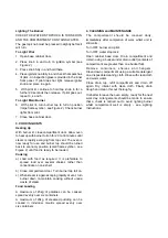
There are four set operating positions as illustrated:
Position 1
Burner and
Pilot OFF.
Position 2
Pilot Ignition or
Pilot ON only.
Position 3
Burner
FULL ON.
Position 4
Burner ON at
economyrate
Figure 2
Because of a built-in safetystop, it is necessaryto
push knob in before trying to turn it from OFF to
IGNITION and from IGNITION to OFF.
Between full on and low rate, the burner can be
regulated as required. Settings will be determined by
experience.


