STEPPII-55/56-LT H
ARDWARE
DESCRIPTION
V
ERSION
1.01
↓
CONNECTION EXAMPLE FOR ANALOG INPUT 1:
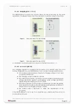
Likewise, on pin 4 (analog input 1) you can install a tachometer generator. Its
functionality is just like pin 2 (analog input 2). The maximum output voltage of the
tachometer is +32 V (see illustrated example in figure below).
Both circuit examples (the NTC (above) and the Tachometer) are only
illustrations to show
the aim of the analog inputs
.
Figure 6:
Connection example for analog input 1
7.1.2.2 Inputs (pin 6, 8, 10, 12)
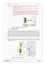
The inputs (pin 6, 8, 10, 12) on the 16-pin connector are high active so they can be
connected to +10.8 ... 32 V DC. The figure below illustrates how to connect these
inputs. If one of the connected pins (inputs) is activated (for at least 1 sec), STEPPII-
55/56-LT will release an alarm (SMS, Voice or data connection). The alarm type and
the alarm text (alarm type SMS) depend on the configuration done by the user. The
inputs can be configured by using the configuration software (Configurator_2.2). All
inputs reserved for customer specific applications can be connected as shown
below:
Figure 7:
Connection example for input 4
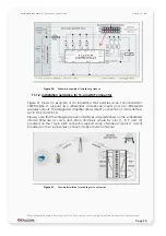
A completed circuit example for all inputs is attached in section
This confidential document is a property of FALCOM and may not be copied or circulated without previous permission
.
Page 33

