FOX3-KMD H
ARDWARE
M
ANUAL
V
ERSION
1.0.1
6.4. LED indicators
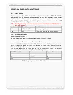
The actual state of the FOX3-KMD can be shown by three LED’s on the front panel of the unit. These
programmable LEDs can be interfaced to show the status of the device.
Figure 10:
View of LED indicators
To turn on one of these LEDs, use the following command:
$PFAL,IO
11
.Set=high
//
11=LED Orange;
$PFAL,IO
12
.Set=
hpulse,2000
//
12=LED Green
;
$PFAL,IO
13
.Set=cyclic,2000,1000
//
13=LED Red;
To turn off these LEDs, use the following command with corresponding index number:
$PFAL,IO
[11,12,13]
.Set=low
6.5. Mounting
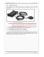
When installing a FOX3-KMD, there are two connectors on the device for connecting a GPS/GNSS antenna such
as FAL-ANT-11
(shown in figure below) or
FAL-ANT-12 from FALCOM. During the installation, please make sure
the receiving side of the GSM/GPS antenna is up, with no metal object above or under the antenna and device
that interfere with GPS reception.
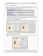
Each of FOX3-KMD device provide 8 holes to be attached to suitable locations (see figure below). It can be
mounted in different directions and different locations such as on wall or in vehicle. Fasteners can be Hexagon
head with collar self drilling screws DIN 7504 K, ST3.5 x 32(12) mm and different length. More detailed
information how to install the device in the vehicle, refer to the application note
"
AppNotes_AVL_Installation_Guide.pdf
".
FOX3-KMD are NOT waterproof or sealed devices. Care must be taken to ensure the devices are kept away from
water or any other liquids.
Figure 11:
View of the mounting holes
This confidential document is a property of FALCOM GmbH and may not be copied or circulated without previous permission.
Page
19
of 23

