H8500A Hydraulic Impact Wrench, Drill and Screwdriver
Greenlee / A Textron Company
4455 Boeing Dr. • Rockford, IL 61109-2988 USA • 815-397-7070
6
Inspection
Clean all parts with an appropriate cleaning solution
and dry them thoroughly. Inspect each component as
described in this section. Replace any component that
shows wear or damage.
1. Motor Cap (47) with Bearings (48): Insert shaft
into bearings. Spin shaft. If the shaft does not spin
smoothly, replace the entire assembly with bearings
already pressed in.
2. Handle (1) with Bearings (3): Insert shaft into bear-
ings. Spin shaft. If the shaft does not spin smoothly,
replace the entire assembly with bearings already
pressed in.
3. Races (36, 38) and Steel Balls (37): Insert all 18
balls (37) into the outer race (36). Install the inner
race (38) over the steel balls. Slide the drive shaft
(39) into the races and spin the shaft. If the shaft
does not spin smoothly, replace the inner race (38)
and steel balls (37). If the outer race (36) is worn or
damaged, replace the entire handle assembly with
the outer race already pressed in.
4. Gear with Internal Bearings (52): Insert a dowel
pin (54) into the bearing. While holding the dowel
between a thumb and forefinger, roll the gear in the
palm of your other hand. Repeat for the other gear.
If either gear does not spin smoothly, replace both
gears with bearings already pressed in.
5. Inspect all other disassembled components for
cracks, grooves or nicks.
Assembly
Refer to the Illustration and Parts List for correct
orientation and placement of parts.
Replace any O-rings, V-rings, seals, and gaskets on
parts that have been disassembled. Apply hydraulic
fluid or O-ring lubricant to all O-rings and all metal
surfaces which they must slide over. When installing
an O-ring which must slide over sharp surfaces, use a
rolling motion and be careful not to damage the O-ring.
Wherever the assembly results in metal-to-metal contact,
coat the surfaces with hydraulic fluid or O-ring lubricant.
Some steps of the assembly procedure require a
removable type of thread sealing and locking compound,
such as Loctite
®
242
®
or equivalent. Follow the manu-
facturer’s instructions for curing.
Motor
1. Use an O-ring tool to install the O-ring (2) into the
handle.
2. Lubricate the outer race (36) liberally with grease.
Install the 18 steel balls (37) into the outer race (36).
Install the inner race (38) over the steel balls.
3. Slide the drive shaft with gear (39) into the races
and through the handle.
4. Install the Woodruff key (41) and one gear (40) onto
the drive shaft (39), guiding the keyway in the gear
over the Woodruff key. Fasten the gear to the drive
shaft with the retaining ring (42).
5. Install the drive pin (44) into the idler shaft (43).
Slide the remaining gear (40) onto the idler shaft,
guiding the keyway in the gear over the drive pin.
Install this assembly into the handle (1), meshing
the two gears (40).
6. Install the dowel pins (45) into the handle. Install the
gasket (46).
7. Assemble the motor cap (47) to the handle (1),
aligning the scribe marks.
8. Apply a removable type of thread sealing and
locking compound, such as Loctite 242 or equivalent,
to the eight cap screws (49). Follow the manufactur-
er’s instructions for curing.
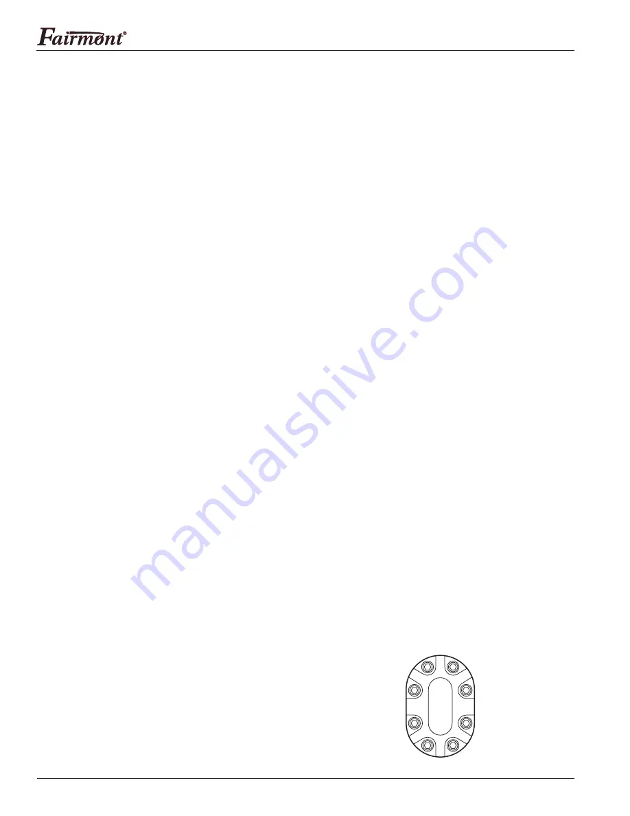
9. Secure the motor cap (47) with the eight cap screws
(49). Using the sequence shown here, torque to
9 newton-meters (80 in-lb).
Torque Sequence
1
3
4
2
5
7
8
6


