Service Manual
UP4
M
IC
P
REAMPLIFIER
October 23, 2009
Fairlight UP-4 Mic Preamp
Page 7
7
Operation in JAPAN, 95-105v supply:
A 100v transformer is fitted, and a USA power cable is supplied. The external voltage selector
switch will be set to 100v (see below); and a T500mA; 250volt rated 20mm long slow-blow
fuse fitted.
Checking or changing the supply voltage setting:
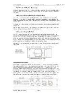
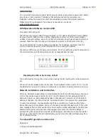
Locate the power input connector on the left of the unit as you face the rear panel. The
bottom of this connector is a voltage selector switch and fuse drawer. The supply voltage
setting is marked at the top of this drawer, nearest the connector pins. (115v is shown on the
diagram below).
To change the voltage setting, turn the power off and disconnect the power cable from the
compressor.
Slide the fuse drawer out with a flat screwdriver, and rotate it through 180 degrees, so that
the new voltage marking is upmost, and push it back in.
Checking or changing the fuse:
Turn the power off and disconnect the power cable. Slide the fuse drawer out with a flat
screwdriver. The fuse fits nearest the inside, and there is space for a spare fuse nearest the
outside. For115v or 100v operation use T500mA, and for 230v use T250mA. (T indicates a
slow-blow type fuse, 20mm long, and all fuses should be 250v rated types). If the fuse fails
in use, and fails when replaced, there is a fault condition, and you must contact the factory to
arrange servicing. Do not attempt repairs or change the fuse value.
WARNING : for continued protection against fire you must ensure that the correct value of
fuse is fitted.
Voltage selector switch and fuse drawer
AUDIO CONNECTIONS
All inputs and outputs are balanced. We have developed a custom output stage capable of
high output currents. This is a non-floating circuit, that has a better noise performance than
possible with the commonly used electronically 'floated' circuit, and better square wave
performance than using a transformer. This means that you must set the outp ut switc hes
located near the output connectors to match the equipment you are connecting to: pin 2 hot
/unbalanced (right position); balanced (middle position), or pin 3 hot /unbalanced (le ft
position). The input connectors can be wired as normal, and because the main signal path is
fully symmetrical, you can chose to wire either as pin 2 or pin 3 hot with no difference.


