background image


Appendix.


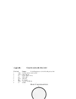
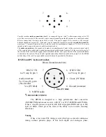
Cassette and audio din socket 


Pin  Lead 

Purpose


Socket diagrams are as viewed looking into socket.


1. 

white 

Cassette ve into switch   

2. yellow 

Audio 

Ground 

3. 

n.c       Aerial changeover o/p 

4.  

grey 

Audio right 

5.  

green 

Audio left 

6. Blue 

12V 

output 

7.


Black 

Cassette switched o/p 

8. n.c Ground 

Black. Ground (metal rim) 


Summary of Contents for RD500

Page 1: ......

Page 2: ...ing the receivers controls 4 1 Auxiliary menu Key 1 ATT HF VHF Attenuator Key 2 AMP Aerial amplifier Key 3 CAS cassette control Key 4 LPF treble cut low pass filter Key 5 AVC automatic volume control...

Page 3: ...menu c Editing d Repeat 4 15 Mode 4 16 Decode and audio interface 4 17 Bands Scanning between frequency limits 4 18 Skip frequencies 4 19 Priority channel 4 20 The on board database system a Memory re...

Page 4: ...s to show the user how easy it can be to use the RD500 and make the most of this exiting new radio We recommend that you read section 3 Getting started which will give a very brief introduction to the...

Page 5: ...labelled 13 8V the centre connector is positive with respect to ground A vehicle power lead should be fused at 1 amp slow blow if a larger fuse type is used fault conditions may damage the receiver s...

Page 6: ...d the aerial Take care when erecting aerials in the vicinity of overhead power lines Rear panel connections 3 Getting started Read This Connect an HF aerial into the main antenna socket or a VHF UHF a...

Page 7: ...dset press ENTER followed by 2 for search all groups The receiver will search for a while then set itself to the first match use the up and down keys to see the other matches Scanning To scan from the...

Page 8: ...e overloaded by strong signals AMP HF Aerial amplifier Aux Key 2 This control connects the HF aerial amplifier and its associated selector switch on the back panel into the aerial path The high impeda...

Page 9: ...number of empty records that are available for use We now return to the main shift key facilities on the receiver press cancel 4 2 BP stereo CW filter SHIFT Key 2 These filter options are active when...

Page 10: ...ming of the response is user presettable for each mode Select the mode Keys 4 to 6 then select the required speed keys 1 to 3 the set up will be permanently stored when the menu is left A slow respons...

Page 11: ...onversation on different frequencies in the way that conventional A B VFO s are used Typically the user may set a VFO on each band SHIFT Key 7 places the cursor below the vfo letter the alphabet lette...

Page 12: ...ly SHIFT Key 9 Clock reveals the clock display Pressing Key 9 a second time reveals the setup screen 1 mode 2 set 3 Timer 4 activate timer a Clock display mode Key 1 gives the clock display menu Press...

Page 13: ...o set the period before shut down Press Key 9 clock and key 4 to activate the timer d Time zones Time zone information relative to GMT is shown in the lower part of the display The standard country ab...

Page 14: ...nd a backup of its entries are required First select new from the file menu and name the new database with the mdb extension for example April mdb then the same process can be followed as with downloa...

Page 15: ...l has gone before moving on to avoid missing part of a two way conversation Pause Only waits on an occupied channel for a short time defined by the user before continuing to scan Hold and pause times...

Page 16: ...des 4 13 Frequency entry fast tuning and fast stepping The receiver s keypad can be used for direct entry of frequencies unless a menu memory or band etc has been selected Any menu can be escaped from...

Page 17: ...records is shown in the lower half of the display Altering the memory formatting will cause a total loss of sound recordings and memory records Cancel will exit from this display Press enter to forma...

Page 18: ...dle of the lock range and if interference is noticed to be coming from an adjacent station ASU upper sideband synchronous or ASL lower sideband synchronous can be used to select the side of the signal...

Page 19: ...y and another key press gives the end frequency a final key press displays the step size At each stage a frequency can be entered from the keypad and mode and the scan type can be set by pressing SHIF...

Page 20: ...se figures are further reduced when the memory is partitioned for sound recording Section 4 14 A memory can be created from a VFO frequency the normal tuning mode after cancelling any other operation...

Page 21: ...f a word can be searched for and the search method is not case sensitive so matches can be made when entries include capital letters To search for a memory press MEM or select a new group and press en...

Page 22: ...S Meter SHIFT UP The S meter can be selected by pressing SHIFT UP and the text display can be reinstated by pressing SHIFT UP again or TEXT ENTER The S meter is calibrated in S units which are equal t...

Page 23: ...olerance is narrower than the tolerance of most p c s so if other manufacturers keyboards are used the keyboards internal clock may have to be trimmed to allow synchronisation of the keyboard to the r...

Page 24: ...cket diagrams are as viewed looking into socket 1 white Cassette switch ve into switch 2 yellow Audio Ground 3 n c Aerial changeover o p 4 grey Audio right 5 green Audio left 6 Blue 12V output 7 Black...

Page 25: ...ceiver to pin 2 of the cassette If the cassette has a jack socket sometimes labled mic pins 4 and 5 of the receiver should be connected to the centre of the jack and a ground connection should be made...

Page 26: ...d to maximise the signal to noise ratio of small signals while the two stage AGC decay shape is tailored to suit SSB speech At VHF three tuned RF filters are provided for preselection in the ranges of...

Page 27: ...This graph shows the response curves for the CW filter selections 9 SPECIFICATIONS...

Page 28: ...eds Aerial inputs 50 ohm inputs High impedance input for HF whip aerial R F attenuator 20dB Audio outputs Stereo line output 0 dB via phono sockets Record input output on din socket External loudspeak...

Page 29: ...1300MHz 50 ohm aerial input for 12dB SINAD I F Filter bandwidths SSB filter 2 4kHz AM Wide Filter 6 kHz NBFM 12 5KHz HF Third order intermodulation 10dBm intercept point Spurious responses 65dB rejec...

Page 30: ...parts and labour Please complete and return this page to receive updates and so that your guarantee can commence Owners name Address Telephone Number Model type e g RD500VX AV10 etc Purchase Serial Da...

Page 31: ......
Reviews: