background image


SMART Pressure Transmitter 


FT3351 Series User Manual


July.2022    

www.Faraboard.com 


15 | 

P a g e


FAHM Co

Industrial Automation 
Doc. FT3351Rev1401-05 


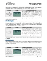
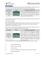
Unit 

(set the unit of 

pressure)


Press <M> until this page is appeared on LCD. Then press 
<Z> to access the units (programing mode). You can select 
the  unit  by  pressing  <S>.  After  that,  press  <Z>  until  all 
characters  blink.  Then  press  <M>  for  the  saving  new 
parameter  and  switching  from  programing  mode  to 
operation mode.  
 

The available units for pressure value are: 

bar 

mbar 

inH2O   

[inch of water at 48ºC] 

inMER   

[inch of Mercury at 0ºC] 

mmH2O  

[millimeter of water at 48ºC] 

cmH2O  

[centimeter of water at 4ºC] 

mH2O   

[meter of water at 4ºC] 

fH2O   

[feet of water at 68ºF] 

cmMER 

[centimeter of mercury at 0ºC] 

mmMER  

[millimeter of mercury at 0ºC] 

mMER  

[meter of mercury at 0ºC] 

PSI 


[pound per square inch] 

PSF 


[pound per square foot] 

G/CM2  

[gram per square centimeter] 

KG/M2  

[kilogram per square meter] 

Pa 


[Pascal] 

KPa 


[kilopascal] 

MPa   

[megapascal] 

HPa 


[hectopascal] 


ATM   

[Atmosphere] 

TORR   

[torr] 

Summary of Contents for HART FT3351 Series

Page 1: ...sure Transmitter FT3351 Series User Manual July 2022 www Faraboard com 1 P a g e FAHM Co Industrial Automation Doc FT3351Rev1401 05 Smart Pressure Transmitter FT3351 Series with HART Revision Selectable Protocol ...

Page 2: ...rations 6 2 3 Installation Process 7 2 3 1 Dimension 7 2 3 2 Mount the Transmitter 7 2 3 3 Housing rotation 10 2 4 Electrical considerations 10 2 4 1 Conduit installation 10 2 4 2 Wiring 11 2 4 3 Grounding 12 3 CONFIGURATION 13 3 1 LCD display 13 3 2 Device setup 13 3 2 1 Device Mode 14 3 2 2 Primary Variable 14 3 2 2 1 Unit 14 3 2 2 2 Max Range and Min Range and Transfer function 16 3 2 2 3 Decim...

Page 3: ...n Doc FT3351Rev1401 05 3 2 4 LCD Parameters 19 3 2 5 Analog Output Parameters 20 Communication Parameters 20 3 2 6 Tank application parameters 21 3 2 6 1 Level unit 22 3 2 6 2 Volume unit 23 3 2 6 3 Mass unit 24 3 2 6 4 Density unit 24 3 2 6 5 Basic parameters 25 3 2 6 6 Desired variable range 26 3 2 7 Reset Factory 27 ...

Page 4: ...e installed within the sensor module and include a temperature sensor a memory module and the capacitance or resistance to digital signal converter A D converter The electrical signals from the sensor module are transmitted to the output electronics in the electronics housing The electronics housing contains the output electronics board the optional local operator Interface LOI buttons and the ter...

Page 5: ...bility to the health of entire electrical loop Local Operator Interface LOI offers easy to use configuration capabilities at the transmitter Selectable HART Revision prepares your plant for the latest HART capabilities while ensuring seamless integration with today s systems Excellent long term stability of 0 1 URL per year Low Temperature Drift of 0 1 URL in full range of ambient temperature 40 8...

Page 6: ...cal national and international standards codes and practices Please review the following safety messages for any restrictions associated with a safe installation In an Explosion Proof Flameproof installation do not remove the transmitter covers when power is applied to the unit Process leaks may cause harm or result in death Install and tighten process connectors before applying pressure Avoid con...

Page 7: ...2 and Figure 3 Figure 3 FT3351 Dimensional Drawings 2 3 2 Mount the Transmitter The FT3551 pressure transmitter can be mounted directly on the manifold A mounting bracket for wall or pipe mounting 2 pipe is also available as an accessory Ideally the pressure transmitter should be mounted in a vertical position to prevent subsequent zero shifts If the transmitter is installed inclined with respect ...

Page 8: ...mportant to mount the transmitter and to lay the process piping so that gas bubbles when measuring liquids or condensate when measuring gases will flow back to the process and not enter the transmitter measuring chamber Different mounting brackets are available shown in Figure 4 Figure 5 and Figure 6 For more information see the Appendix Figure 4 Differential Pressure transmitter mounting diagrams...

Page 9: ...r FT3351 Series User Manual July 2022 www Faraboard com 9 P a g e FAHM Co Industrial Automation Doc FT3351Rev1401 05 Figure 5 Type B pressure transmitter mounting diagrams Figure 6 Type C pressure transmitter mounting diagrams ...

Page 10: ...housing rotation the housing stop tang screw has to be unscrewed by approximately 1 rotation do not pull it out and once the desired position has been reached retightened Figure 7 Housing rotation 2 4 Electrical considerations Make sure all electrical installation is in accordance with national and local code requirements 2 4 1 Conduit installation If all connections are not sealed excess moisture...

Page 11: ...ove the cover in explosive atmospheres when the circuit is live Signal wiring supplies all power to the transmitter 2 For 4 20 mA HART output connect the positive lead to the terminal marked and the negative lead to the terminal marked Do not connect powered signal wiring to the test terminals Power could damage the test diode 3 Plug and seal unused conduit connection on the transmitter housing to...

Page 12: ...t the power supply end For 4 20 mA HART output the signal wiring may be grounded at any one point on the signal loop or may be left ungrounded The negative terminal of the power supply is a recommended grounding point Always ground the transmitter case in accordance with national and local electrical codes The most effective transmitter case grounding method is a direct connection to earth ground ...

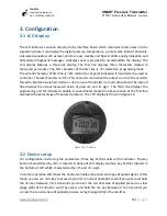
Page 13: ...nt of transmitter forced to fixed value via hart device or due to use of transmitter in multi drop mode The second line displays the actual measured value of pressure and its sign The third line displays the engineering unit for indicated variable A speed meter located in above section of the first line displayed the percentage of measured pressure The LCD display is shown in Figure 10 3 2 Device ...

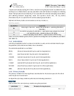
Page 14: ...d variable as basic calculation The selectable application are as follow PRESS Pressure measurement may be used in all applications LEVEL level measurement may be used in tank application VOLUME volume measurement may be used in tank application MASS mass measurement may be used in tank application V FLOW volumetric flow measurement may be used in orifice application M FLOW mass flow measurement m...

Page 15: ...ameter and switching from programing mode to operation mode The available units for pressure value are bar mbar inH2O inch of water at 48ºC inMER inch of Mercury at 0ºC mmH2O millimeter of water at 48ºC cmH2O centimeter of water at 4ºC mH2O meter of water at 4ºC fH2O feet of water at 68ºF cmMER centimeter of mercury at 0ºC mmMER millimeter of mercury at 0ºC mMER meter of mercury at 0ºC PSI pound p...

Page 16: ...ration mode Min pressure The pressure mapped to 4 mA Press M until this page is appeared on LCD Then press Z to access the amount of minimum pressure programing mode You can change the amount of digits by S and change the point and position of digits by Z After tuning this parameter press the Z until all characters blink Then press M for the saving new parameter and switching from programing mode ...

Page 17: ...after set damping value with a linear curve parameter display Parameter tuning structure Damping for smoothing the noisy output based on sec Press M until this page is appeared on LCD Then press Z to access the amount of time based on second programing mode You can change the amount of digits by S and change the point and position of digits by Z After tuning this parameter press the Z until all ch...

Page 18: ... variable represents the maximum value According to transfer function selected by user for value between min and max pressure values the custom variable value will be produced with linear or square root curve parameter display Parameter tuning structure Custom Variable Max Range The value mapped to 20 mA Press M until this page is appeared on LCD Then press Z to access the amount of maximum value ...

Page 19: ...the current value of output signal diagnostic signs like SQRT FIX Locked Over range and Under range signs and also implementation of configuration menu list User can select one or two variable to display on LCD in idle mode If user select more than one variable to show LCD will display selected variables alternately parameter display Parameter tuning structure LCD Mode configuring LCD to show your...

Page 20: ... set the alarm for over range high and under range low or maintain the last value Last by pressing S After that press Z until all characters blink Then press M for the saving new parameter and switching from programing mode to operation mode Test Trim Current Simulate the output current to fix value and or trim the current Press M until this page is appeared on LCD Then press Z to access the test ...

Page 21: ...l volume math or density of liquid in the tank The main formulas for calculating the user s desired variable are as bellow 𝑃 ρ g h h v A h 𝑚 ρ v ρ is density of liquid g is the gravity of earth h is the current height of liquid in the tank h is the position of transmitter relative to tank floor v is the current volume of liquid in tank m is the current mass of liquid in the tank and A is the tank ...

Page 22: ... output HRV Configuration of tank application is performed via following parameters 3 2 6 1 Level unit User can select the tank level unit using this parameter parameter display Parameter tuning structure Level Unit set the unit of level Press M until this page is appeared on LCD Then press Z to access the units programing mode You can select the unit by pressing S After that press Z until all cha...

Page 23: ...ccess the units programing mode You can select the unit by pressing S After that press Z until all characters blink Then press M for the saving new parameter and switching from programing mode to operation mode The available units for tank volume are GAL gallon LITER liter IGAL imperial gallon METER3 cubic meter BARREL barrel BUSHEL bushel YARD3 cubic yard FEET3 cubic feet INCH3 cubic inch BBL bbl...

Page 24: ...ation mode The available units for tank mass are G gram KG kilogram POUND pound STON standard ton LTON long ton OUNCE ounce 3 2 6 4 Density unit User can select the liquid density unit using this parameter parameter display Parameter tuning structure Density Unit set the unit of density Press M until this page is appeared on LCD Then press Z to access the units programing mode You can select the u...

Page 25: ...digits by S and change the point and position of digits by Z After tuning this parameter press the Z until all characters blink Then press M for the saving new parameter and switching from programing mode to operation mode Tank Volume The total volume of tank Press M until this page is appeared on LCD Then press Z to access the amount of tank volume programing mode You can change the amount of dig...

Page 26: ... of output signal After this configuration the output signal will be mapped to min and max values So when the desired variable be equal to LRV the output signal will be 4 0mA and when it be equal to HRV the output signal will be 20 0mA parameter display Parameter tuning structure LRV The lower range value mapped to 4 mA Press M until this page is appeared on LCD Then press Z to access the amount o...

Page 27: ...red min and max value otherwise device will not accept the user changes Ordinary this type of pressure transmitters supports 1 100 turn down ratio So the difference between min and max value should be greater than Sensor Range 100 For more accurate configuration please refer to pressure transmitter datasheet 3 2 7 Reset Factory User can recall all factory settings using bellow menu The default pas...

Page 28: ...SMART Pressure Transmitter FT3351 Series User Manual July 2022 www Faraboard com 28 P a g e FAHM Co Industrial Automation Doc FT3351Rev1401 05 ...

Reviews: