background image

50

OPERATION 

Timer countdown can be set independently for all cooking zones. 

Timer

Timer function makes cooking easier by making it possible to set Duration. It can also be used 

as a Kitchen Timer.

Set the Timer

Timer function allows the cooking zone to be switched off after the set time has elapsed. The 

timer function can only be set when a cooking zone is operating (heat setting is greater than 

"0"). The timer function can be set independently for all individual cooking zones. Timer count-

down can be set from 1 to 99 minutes.

To set the timer:

●  select a cooking zone by touching cooking zone selection sensor field (

3

) and select the 

desired heat setting from 1 to 9 by sliding your finger across the heat setting selection sen-

sor field (

2

). The display will show the selected heat settings from 1 to 9.

●  then, during the next 10 seconds, touch the Timer selection sensor field (

4

). "

00

" will be 

shown on the Timer display (

4

) and the appropriate Timer activation indicator light (

5

) will 

light up to indicate activation of the Timer function for the relevant cooking zone.

●  Now, select the desired Timer setting by sliding your finger across the setting selection 

sensor field (

2

). The second digit is set first and the first digit is set next. Once the second 

digit is set, touch the sensor (

4

) again to set the first digit. If you do not set any value for the 

first digit within 10 seconds, the value will be set to "

0

"(eg."

06

").

  The countdown starts when the Timer activation indicator light (5) starts flashing.

If more than one timer is set the shortest duration is displayed. Timer indicator 

light (5) of a relevant cooking zone will flash.

Change Timer Duration

Check Timer Duration

To check progress of Timer countdown at any time, touch the timer sensor field (

4

). Timer 

indicator light (

5

) of a relevant cooking zone will flash.

Programmed Timer setting can be changed at any time.

To change the programmed Timer setting, select a cooking zone by touching the cooking zone 

selection sensor field (

3

), and then touch the Timer selection sensor field (

4

).

Summary of Contents for IO-HOB-1172

Page 1: ...IF 33B3S 3IF 331B3S Manual de instrucciones EN Induction hob Lea detenidamente este manual antes de usar el aparato Before using the appliance please carefully read this manual Instruction manual ES E...

Page 2: ...No utilice el aparato sin haber le do este manual El aparato s lo ha sido dise ado como dispositivo para cocinar Cualquier otro uso por ejemplo para la calefacci n de habitaciones es incompatible con...

Page 3: ...3 CONTENIDO Informaci n b sica 2 Seguridad 4 Descripci n del producto 9 Instalaci n 10 Funcionamiento 14 Limpieza y conservaci n 25 Situaciones de emergencia 27 Datos t cnicos 29...

Page 4: ...a y conocimientos siempre que lo hagan bajo la supervisi n de otra responsable de su seguridad o sigan las instrucciones de uso Impida que los ni os jueguen con el aparato y que realicen las tareas de...

Page 5: ...o cuchillos tene dores cucharas o tapas as como papel de aluminio ya que pueden calentarse Despu s de su uso apague el elemento de calefac ci n de la placa mediante el interruptor y no tenga en cuenta...

Page 6: ...uarios que porten dispositivos de apoyo a las funciones vitales por ejemplo marcapasos bomba de insulina o aud fono deben asegurarse que el funciona miento de stos no se ve afectado por la placa de in...

Page 7: ...o tensi n No se puede utilizar la superficie de la placa como una tabla de cortar o mesa de trabajo No se debe colocar la placa encima de un horno sin ventilador lavavajillas frigor fico congelador o...

Page 8: ...as nocivas consecuencias para el ser humano y para el medio ambiente derivadas de la presencia de componentes peligrosos o del inadecuado almacenamiento y proce samiento de dichos dispositivos Este ap...

Page 9: ...erdo 1 2 3 3 3 4 5 6 7 8 9 10 11 5 1 Sensor encender apagar la placa 2 Sensor de cambio de potencia de cocci n 3 Indicador de la zona de calentamiento 4 Indicador del reloj 5 Diodo de se alizaci n del...

Page 10: ...ancia m nima entre el borde del hueco y la pared lateral del mueble deber ser de 55 mm l El revestimiento y el pegamento de los muebles para empotrar debe ser resistente a temperaturas superiores a 10...

Page 11: ...N Est prohibido colocar la placa encima de un horno sin ventilaci n Dib 2 Montaje de la encimera encima del armario Montaje de la encimera encima del horno con ventilaci n 5 10mm 5 10mm 500x10mm 25mm...

Page 12: ...la sim tricamente de forma que la distancia entre la placa y el borde de la encimera sea uniforme en cada lado fig 5 Instalaci n de la junta Dependiendo del modelo la junta vendr instalada de f brica...

Page 13: ...l ctrica lea la informaci n in cluida en la placa de datos y en el esquema de conexi n Advertencia El instalador debe entregarle al usuario el certificado de conexi n de la placa a la instalaci n el c...

Page 14: ...nte sobre la placa y termina en el momento de retirarlo Durante el uso habitual de la placa de inducci n pueden o rse diferentes sonidos que no afectan de ninguna manera al correcto funcionamiento de...

Page 15: ...idas y si se contin a presionando desencadena una se al de fallo Al terminar el uso apague la zona de calentamiento mediante el ajuste y no tenga en cuenta las indicaciones del detector de recipientes...

Page 16: ...ndo influir negativamente en el control de temperaturas por el m dulo de inducci n y podr causar el sobrecalentamiento del recipiente No debe usar recipientes da ados por ejemplo con el fondo deformad...

Page 17: ...ecta la presencia de olla Las ollas de fondo de cobre No detecta la presencia de olla Para la cocci n por inducci n s lo se deben utilizar recipientes ferromagn ticos fabricados con materiales tales c...

Page 18: ...1 dentro de los siguientes 10 segundos deber conectar la zona de calentamiento seleccionada 3 1 Despu s de tocar el sensor que indica la zona de calentamiento seleccionada 3 en el ndice del grado de l...

Page 19: ...ci n Booster lo cual se se ala con la aparici n de la letra P en la pantalla de la zona de cocci n 3 La desactivaci n de la funci n Booster se realiza presionando el sensor 2 y reducir la potencia de...

Page 20: ...a se lleva a cabo me diante el sensor 9 manteniendo el sensor durante 5 segundos La activaci n de la fun ci n de bloqueo se indica mediante la iluminaci n del diodo de se alizaci n 10 Durante un corte...

Page 21: ...ctivarse mediante el sensor 5 Luego con el sensor 2 moviendo con el dedo fijamos la potencia entre 1 y 8 y volvemos a apretar el sensor 3 En la pantalla se mostrar intermitente mente el d gito de la p...

Page 22: ...Tras fijar el segundo d gito debemos apretar el sensor 4 y fijaremos el primer d gito Cuando no fijemos ning n valor para el primer d gito y pasen 10 segundos el reloj tendr el valor 0 por ejemplo 0...

Page 23: ...gundos se debe seleccionar el sensor de la activaci n de tem porizador 4 En el indicador de temporizador 4 aparecer n los d gitos 00 Tras activar el temporizador a trav s del sensor 2 se debe fijar el...

Page 24: ...de cocci n de 42 C Apretamos el sensor de la funci n de cocci n por segunda vez 8 lo cual se se ala con la iluminaci n en la pantalla del s mbolo doble horizontal significa seleccionar el nivel de coc...

Page 25: ...s que limpian con vapor Eliminaci n de las manchas Las manchas claras de color perla resi duos de aluminio pueden desaparecer de la placa de inducci n utilizando un detergente especial cuando est fr a...

Page 26: ...rvan grietas o roturas en la placa cer mica deber apagarla inmediatamente y desconectarla de la red quitando el fusible o tirando de la clavija de la toma A continuaci n llame al servicio t cnico Revi...

Page 27: ...sar los botones durante un poco m s de tiempo Se han pulsado al mismo tiempo demasiados boto nes Pulsar siempre s lo un bot n excepto cuando se apaga la zona de calenta miento 3 El dispositivo no res...

Page 28: ...e su correcta utilizaci n en el hogar La garant a no cubrir aquellos fallos de funcionamiento que se deban a errores que Usted haya cometido El fabricante no responde de los da os producidos en el apa...

Page 29: ...n 210 220 mm 2000 W Zona de calentamiento de inducci n 290 mm 2600 W Zona de calentamiento de inducci n Booster 210 220 mm 2000 3000 W Zona de calentamiento de inducci n Booster 160 180 mm 1200 1400W...

Page 30: ...u have read and understood this manual thoroughly The appliance is designed solely for cooking Any other use eg heating a room is incompatible with the appliance s intended purpose and can pose a risk...

Page 31: ...31 CONTENTS Basic Information 30 Safety instructions 32 Description of the appliance 37 Installation 38 Operation 42 Cleaning and maintenance 53 Troubleshooting 55 Specification 57...

Page 32: ...ack of experience and knowledge if they have been given supervision or instruction concerning use of the appliance in a safe way and understand the hazards involved Children shall not play with the ap...

Page 33: ...nives forks spoons and lids should not be placed on the hob surface since they can get hot After use switch off the hob element by its control and do not rely on the pan detector The appliance is not...

Page 34: ...sory handicaps or by those who are inexperienced or unfamiliar with the appliance unless under supervision or in accordance with the instructions as communicated to them by persons responsible for the...

Page 35: ...racked switch off power to avoid the risk of electric shock Do not use the cooking surface as a cutting board or work table Do not place metal objects such as knives forks spoons lids and aluminium fo...

Page 36: ...avoid environmental and health hazards resulting from the pre sence of dangerous components and the in appropriate storage and processing of such goods In accordance with European Directive 2012 19 U...

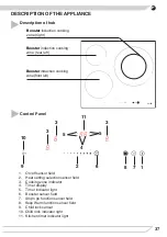
Page 37: ...ion cooking zone front left 1 2 3 3 3 4 5 6 7 8 9 10 11 5 1 On off sensor field 2 Heat setting selection sensor field 3 Cooking zone indicator 4 Timer display 5 Timer indicator light 6 Booster sensor...

Page 38: ...worktop l The distance between the edge of the opening and the side wall of the furniture should be minimum 55 mm l Worktop must be made of materials including veneer and adhesives resistant to a tem...

Page 39: ...tall the hob above the oven without ventilation Fig 2 Installing hob in kitchen cabinet worktop Installing hob in kitchen worktop above oven with ventilation INSTALLATION 5 10mm 5 10mm 500x10mm 25mm 3...

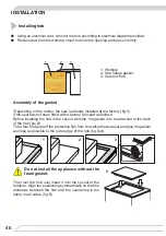
Page 40: ...ted at the factory proceed as follows Before installing the hob in the cut out worktop the gasket is to be attached to the back of the hob pic 2 To do this first peel off the protective film from the...

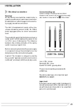
Page 41: ...connecting the hob to the power supply it is important to read the information on the data plate and the connection diagram Caution The installer is obliged to provide the user with appliance electri...

Page 42: ...no thermal inertia since the cooking starts immediately when the pot is placed on the hob and ends once it is removed Certain sounds can be heard during normal use of the induction hob which do not a...

Page 43: ...me a sensor field is touched an acoustic signal can be heard OPERATION If a pan is not placed on a cooking zone or the pan is unsuitable the symbol is displayed The cooking zone will not operate If a...

Page 44: ...the induction module The concave base or deep embossed logo of the manufacturer interfere with the temperature induction control module and can cause overheating of the pot or pan Do not use damaged...

Page 45: ...th base is recom mended Glass Cookware is not detected Porcelain Cookware is not detected Cookware with copper base Cookware is not detected For induction cooking us only ferromagnetic base materials...

Page 46: ...itch on the cooking zone Once the appliance is switched on using the on off touch sensor 1 select a cooking zone 3 within the next 10 seconds 1 When a cooking zone selection sensor field 3 is touched...

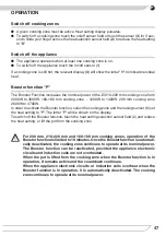
Page 47: ...er function select the cooking zone and then using sensor 6 set the heat setting to P The letter P will be shown on the display To switch off the Booster function touch the heat setting selection sens...

Page 48: ...d Lock Turn Child Lock on off Touch and hold sensor 9 for 5 seconds to turn Child Lock on off Indicator light 10 is on when the Child Lock function is on The H residual heat indicator is not displayed...

Page 49: ...ivate the se lected cooking zone Then sliding your finger across the setting selection sensor field 2 set the desired heat setting in the 1 8 range and then touch sensor field 3 again The display will...

Page 50: ...lay 4 and the appropriate Timer activation indicator light 5 will light up to indicate activation of the Timer function for the relevant cooking zone Now select the desired Timer setting by sliding yo...

Page 51: ...sensor field 4 Kitchen timer display 4 will show 00 Now select the desired Timer setting by sliding your finger across the setting selection sensor field 2 The second digit is set first and the first...

Page 52: ...d Touch Keep Warm function sensor field 8 again and the second symbol will be shown indicating that temperature of 70 C is selected Touch Keep Warm function sensor field 8 again and the third symbol w...

Page 53: ...team or pressure cleaners Removing stains Bright stains of pearl colour residual aluminium can be removed from the cool hob using a special cleaning agent Limestone residue eg after evaporated water c...

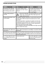
Page 54: ...nd contact customer service Important In the event of breakage or chipping of the hob cooking surface turn off and unplug the appliance To do this disconnect the fuse or unplug the appliance Then refe...

Page 55: ...r multiple sensors touched at the same time always touch only one sensor field except when a cooking zone is switched off 3 The appliance does not respond and emits and extended beep improper use wron...

Page 56: ...centre Important You are responsible for operating the appliance correctly and maintaining its good condition If you call service as a result of operating the appliance incorrectly you will be respon...

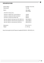
Page 57: ...200 W induction cooking zone 210 220 mm 2000 W induction cooking zone 290 mm 2600 W booster induction cooking zone 210 220 mm 2000 3000 W booster induction cooking zone 160 180 mm 1200 1400 W booster...

Page 58: ...58...

Page 59: ...59...

Page 60: ......

Reviews: