Fagor Innova 40i Installation And Operation Manual Download Page 37

40i - Installation/Operation - DRO installation - (36/40)

4.6.5.2

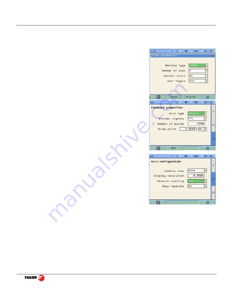
Parameters for the threading function

In Feedback properties set Z2 as Rotary axis type (Z2 reads the pulses of the encoder connected to the
leadscrew in the lathe). Then, follow the instructions on the screen to complete the configuration of Z2:
number of pulses of the encoder and the leadscrew pitch of the lathe in millimeters or inches.
Access the DRO, AXIS and FEEDBACK parameters as
described in the previous sections and set them as follows:

Machine type:

 Lathe

Number of axes:

 3

Default units:

 mm or inches.

Type of axis

: Rotary.

Number of pulses

: Depends on encoder.

Pitch

: Depends on leadscrew/ballscrew. In millimeters (mm) or

threads per inch (tpi).

Note

: If the polarity of the Z axis linear encoder needs to be

reversed, follow steps below for Z1.

Change Reverse Counting to Yes.
It will ask you if you want to save parameters. Press Yes.

Summary of Contents for Innova 40i

Page 1: ...Innova 40i 40i B Installation Operation Manual Manual code 14460086 Manual version 1501 Software version 2 50 ...

Page 2: ...ols and references 7 2 4 1 Tools 7 2 4 1 1 Tool change 7 2 4 1 2 Set a new tool in the table 7 2 4 1 3 Tool compensation 8 2 4 2 Reference 8 2 4 2 1 Changing the reference 9 2 4 2 2 Setting part zero datum as instructed by the assistant 9 2 4 2 3 Setting part zero datum without using the assistant 10 2 4 2 4 Searching the center of a part 10 2 5 Special functions 11 2 5 1 Bolt hole drilling 11 2 5...

Page 3: ...ection connector X5 26 4 5 3 Power and machine connection 27 4 6 Installation parameters 28 4 6 1 Accessing installation parameters 28 4 6 2 User parameters 28 4 6 2 1 Language 28 4 6 2 2 Screen color 29 4 6 3 Installer parameters 29 4 6 3 1 Parameter backup into USB memory 29 4 6 3 2 DRO 29 4 6 3 3 Feedback 31 4 6 3 4 Compensation 33 4 6 4 Test mode 34 4 6 5 Threading 35 4 6 5 1 Installation Inst...

Page 4: ...creen comes up for a few seconds and then the work screen is displayed Turns the DRO on or off TFT screen Select axes Delete axis Preset Keys for entering numeric values Validate or access to SET Power indicator LED Keys to open droplist buttons of the FUNCTION BAR Power off button Cursor keys Tool compensation on off Toggle between Z Z1 and Z2 in lathe mode with 3 axes Abort an operation already ...

Page 5: ...s mm inch Display mode INC ABS Set Clear Chronometer DISPLAY AREA STATUS BAR FUNCTION BAR Probe ON Home search Setup Setup CHANGE Reference Part datum Part center Tool Tool setting Tool table DISPLAY FUNCTION Bolt hole drilling Linear drilling Grid pattern drilling Go to Calculator Inc Abs mm inch Set Clear Deg DMS Rad Diam TOOL Set tool Nr Teach in Tool table DISPLAY FUNCTION Angle measurement Tu...

Page 6: ... position and drill the hole Move the axis until the display reads 37 000 C position and drill the hole Move the axis until the display reads 62 000 D position and drill the hole 2 1 2 2 Incremental mode The coordinate is referred to the previous point where the axis display has been set to zero The example on the right would be carried out as follows starting at point A Move the axis until the di...

Page 7: ...et on the display or zero it Clear 2 2 1 In Set mode indicated with an S on the upper status bar To preset a value for an axis To zero the axis either preset a 0 value using the previous keystroke sequence or use this other sequence clear axis 2 2 2 In Clear mode indicated with a C on the upper status bar Set the display to zero To preset a value And validate the data by pressing this key Or ignor...

Page 8: ...will show the position value preset in parameter user offset see Reference This icon indicates that the axis must be homed Note When all the required axes are homed the DRO automatically leaves the home search mode 2 4 Tools and references 2 4 1 Tools Change to or set tool diameter and length It offers a 15 tool table 2 4 1 1 Tool change It becomes the current tool 2 4 1 2 Set a new tool in the ta...

Page 9: ...ed in two axes at the same time Tool compensation on off for this corner of the pocket Tool compensation on off for this corner of the pocket Tool compensation on off for this corner of the pocket Tool compensation on off for this corner of the pocket 2 4 2 Reference Change part reference datum set a new one or search the center of the part There are 100 references or datum points that may be set ...

Page 10: ...the tool being used Z axis Activate Z axis homing Optional Activate the probe mode if the probe has been configured and it is being used Select the Z axis to set the datum point on the vertical axis Sequence to follow Set or change the tool Move the tool to the first side until it touches the part Press Enter Move the tool to the second side until it touches the part Press Enter If the vertical ax...

Page 11: ... to zero 2 4 2 4 Searching the center of a part Set or change the tool It activates the probe mode If the probe has been set it may be used to touch the desired sides of the part Move the tool to the first point Press ENTER Move the tool to the second point Press the key of the axis whose center you re trying to find The display of the axis whose center you re searching shows a value that is half ...

Page 12: ...illing It allows up to 99 holes to be drilled in line in different planes XY XZ YZ without having to calculate the coordinates X Y of each hole by simply keying in some basic data Select plane X Y Position of the first hole Distance between holes Number of holes Alpha Inclination of the line of holes 2 5 3 Grid pattern drilling It allows up to 99holes to be drilled in grid or frame pattern in diff...

Page 13: ...e on an axis press ENTER to go on to the next axis and validate the data just entered 2 5 5 Calculator function It may be used to carry out mathematical and trigonometric operations as well as preset the desired axis with the result of the calculation or import the displayed coordinate values into the calculator to carry out math operations Different types of calculators may be selected at the fun...

Page 14: ...movement views and sections or 3D Consists of a top view and two sections with a mobile partition by pressing the arrow keys The 3D graphic may be rotated using the arrow keys Opens the window for entering the actual real part dimensions Viewing the simulation in real mode requires entering the real X Y Z dimensions of the part Tool movement Function Bolt hole drilling Linear drilling Grid pattern...

Page 15: ...ess the Z axis key The Z axis display reads zero Press Enter A window opens for entering the hole depth Press Enter to validate The entered depth value is shown on the Z axis display Move the Z axis until its display reads zero This way the hole is drilled with the indicated depth Press this key to show the coordinates of the next drilling position hole Repeat these steps until all the holes of th...

Page 16: ...8 Stop bits 1 Parity none From the left column to the right the values correspond to the 1st 2nd and 3rd axis respectively For example 100 000 132 035 0 435 133 005 132 035 0 435 870 020 132 435 0 435 133 870 132 035 0 435 191 890 205 545 10 540 2 5 7 1 Turn the probe ON and OFF Connect a USB memory to the DRO and wait for 4 seconds for the DRO to configure the memory To turn the probe mode ON The...

Page 17: ... the actual distance traveled by the tool When this mode is active the X axis display shows the sign In radius mode the X axis display shows the actual distance traveled 3 1 4 inc abs ñ Toggle between incremental and absolute feedback reading counting The status bar shows the currently active mode 3 1 4 1 Absolute mode In this mode the coordinates position values are referred to part zero Example ...

Page 18: ... 63 6 until obtaining the desired diameter 3 2 Tool Set or change the tool Up to 100 tool offsets may be defined at this DRO from tool 0 to tool 99 The unit stores in its internal memory the relative offsets of all the tools with respect to that of tool 0 master tool Therefore if tool 0 has been preset in ABS mode on X and Z and then the rest of the tools it will suffice to just preset the master ...

Page 19: ... axis until the tool touches the part Press HOLD for both axes Remove the part and measure it Preset the X axis with the measured diameter value Preset the value for the Z axis Press button to validate These tool presets are kept in memory even when the unit is powered off up to a maximum of 10 years Notes The presets done with any tool in incremental mode change the part zero for all the tools If...

Page 20: ...on to enter the position value on the X axis If the part diameter is known its value may be entered directly Press Enter The next field box is activated Z Initial Z axis value Place the tool touching the part on the Z axis Preset a value and press the button for the Z axis to enter the value of the Z axis display Press Enter The next field box is activated X Enter final diameter Press Enter Z Ente...

Page 21: ...near scale feedback that s attached to Z axis The middle LED bars are for the encoder feedback that s attached to the leadscrew The bottom bar shows the distance to go Setup When beginning to work depending on the encoder position sometimes it is impossible to engage the axis So with the machine stopped move the Z axis position just to get one rectangle close to the other one of the colored rectan...

Page 22: ...e thread we do recommend engaging the machine in the same color as the previous cycle to improve the final result of the thread Distance to go bar DTG As the Z axis feedback and the encoder feedback LED bars approach each other the white bar will increase size When the DTG turns fully green the LED bars should be aligned and ready to engage lever 3 3 4 Calculator function See section 2 5 5 Calcula...

Page 23: ... on to the support arm using two set screws 4 2 Mounting of the built in model The DRO is ready to be built into an operator panel or pendant The name of this model is special a B has been added at the end of the product name Example INNOVA 40i B Dimensions of the DRO and the window to insert it into The first figure shows the DRO dimensions The second figure shows the dimensions of the hole neede...

Page 24: ...oder X5 SUB D type 9 pin female connector for the probe USB connector In order to comply with UL standards this unit must be connected in the final application using a listed detachable cord set BLEZ with a molded three prong plug and a suitable fitting to be connected to the equipment rated minimum 300 V AC The cord type shall be SO SJO or STO Suitable Strain Relief means must be provided in the ...

Page 25: ...er outages of up to 20 milliseconds 10 year memory backup of installation parameters when the unit is off The operating temperature inside the DRO enclosure must be between 5 ºC and 45 ºC 41 ºF and 113 ºF The storage temperature inside the DRO enclosure must be 25 ºC and 70 ºC 13 ºF and 158 ºF Maximum relative humidity 95 non condensing at 45 ºC 113 ºF Front Panel Sealing IP54 DIN 40050 Rear panel...

Page 26: ...oidal signal It admits SSI communication for absolute encoders Maximum frequency 250 KHz minimum gap between flanks 950 nsec Phase shift 90º 20º hysteresis 0 25 V Vmax 7V maximum input current 3mA High threshold logic state 1 2 4 V VIH 5 V Low threshold logic state 0 0 0 V VIL 0 55 V Feedback connection Connectors X1 X2 and X3 Pin Signal 1Vpp TTL Signal SSI Function 1 A Input for feedback signals ...

Page 27: ...V High threshold logic state 1 VIH From 12 5 V DC on Low threshold logic state 0 VIL Below 4 V DC Maximum nominal voltage Vimax 35 V DC The unit has two probe inputs 5 V DC and 24 V DC at connector X5 Depending on the connection being used it is possible to choose whether it is activated by the up flank or by the down flank of the probe see section 4 6 3 2 DRO en la página 29 Probe connection Conn...

Page 28: ...nnection Always mount it vertically so its keyboard is within operator s reach and its digits are easily visible at operator s eye level Do not connect or disconnect the DRO connectors while it is under power Connect all metallic parts to a common point on the machine tool and it to the general ground point Use cables of enough gage no thinner than 8 mm 2 for this connection Acts with an up flank ...

Page 29: ...encoder or when doing a repair They are parameters related to the machine feedback and to the DRO itself 3 TEST MODE To check the various status of different elements of the DRO such as screen keyboard etc For the installer only Accessing the test mode requires a password Password 231202 4 6 2 User parameters Parameters that may be modified by the user change the language set the chronograph and s...

Page 30: ...to save and recover DRO parameters Multi point compensation tables User programs 4 6 3 2 DRO It configures the DRO for each type of machine Number of axes type of machine mill lathe etc Pressing this button opens the window shown on the right The following items are set in it 1 Type of machine Mill or lathe 2 Number of axes to display 1 2 or 3 3 Default units mm or inches 4 Toggled by the user Yes...

Page 31: ...this option YES the screens shows a window indicating the feed rate of each axis The units will be m min or inches min depending on whether MM or INCH is active The names of the axes may also be changed instead of calling them X Y or Z Alarms option Turn on off the various types of alarms These alarms must be set for each axis The following screen is displayed 1 1 Vpp alarm The DRO checks the ampl...

Page 32: ...een to set the characteristics of the encoder They are parameters for each axis The sections to be set are 1 Type of axis Linear or rotary 1 1 LINEAR It requests the resolution of the linear encoder 1 2 ROTARY It requests the number of pulses turn of the encoder and the number of turns the encoder must make for the machine to consider a 360º movement mechanical gear ratio For SSI the number of bit...

Page 33: ...tch graduated glass with 1 micron resolution Therefore a 1 micron resolution would require a sinusoidal multiplying factor of 5 If the feedback signal is TTL with NO distance coded reference marks like GX FT SY etc the value for this parameter will be 1 2 3 SSI It is the protocol used to communicate with absolute encoders This protocol is configured with the following parameters Resolution Only re...

Page 34: ...the DRO is turned on it forces a home search It is recommended to set it to YES when the DRO uses positioning error compensation because if the compensated axis is not homed the compensation will not be applied Type It sets the homing system of the linear encoder NONE NORMAL INCREMENTAL or DISTANCE CODED When selecting DISTANCE CODED you must set the engraving pitch of the linear encoder 20 µm 40 ...

Page 35: ... at least one point with no error error 0 Different options are offered when the Function button is pressed Exit To exit the screen saving the data Draw Graph Draws a graph with the points and errors entered It is recommended to check the graph to detect possible mistakes made when entering data 4 6 4 Test mode It may be used to know system information such as software version hardware version sof...

Page 36: ...ng off of it Here is an example of a shaft that was made to connect to the encoder Note AF Coupling will be connecting the shaft to the encoder You will have to make up a bracket to secure the encoder onto the machine Here is an example of a bracket made up to mount to the machine The encoder and AF Coupling are attached to the bracket as another example Connect the shaft to the AF Coupling Align ...

Page 37: ...leadscrew pitch of the lathe in millimeters or inches Access the DRO AXIS and FEEDBACK parameters as described in the previous sections and set them as follows Machine type Lathe Number of axes 3 Default units mm or inches Type of axis Rotary Number of pulses Depends on encoder Pitch Depends on leadscrew ballscrew In millimeters mm or threads per inch tpi Note If the polarity of the Z axis linear ...

Page 38: ...g regulations 5 2 1 1 Electromagnetic compatibility EN 61000 6 2 2005 Standard on immunity in industrial environments EN 61000 6 4 2007 Standard on emission in industrial environments According to the European Directive 2004 108 CE on electromagnetic compatibility In Mondragón September 1st 2009 5 2 2 Safety conditions Read the following safety measures in order to prevent damage to personnel to t...

Page 39: ...ronment This unit is ready to be used in Industrial Environments complying with the directives and regulations effective in the European Community Install this DRO vertically so its power switch of the back panel is at a distance between 0 7 m 27 5 inches and 1 7 m 5 6 ft off the floor and away from coolants chemical products blows etc that could damage it Keep it away from direct sunlight extreme...

Page 40: ...ct was launched up to 8 years after such product has disappeared from the product catalog It is entirely up to FAGOR to determine whether a repair is to be considered under warranty EXCLUDING CLAUSES The repair will take place at our facilities Therefore all shipping expenses as well as travelling expenses incurred by technical personnel are NOT under warranty even when the unit is under warranty ...

Page 41: ...ernal circuits of the equipment especially in high humidity conditions To clean the equipment nonabrasive dish washing detergents are recommended in liquid never powder form or 75 isotropic alcohol with a clean cloth DO NOT USE aggressive solvents benzol acetones etc which could damage the materials the equipment is made with Do not use high pressure compressed air to clean the item as this could ...

Reviews: