


DC Servo Drive System Manual Ver: 0009
DC - 24/32
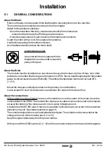
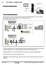
Encoder feedback connection.
The encoder signals must be taken to the ENCODER INPUT of the DCS.
The DCS amplifies these signals and it sends them out through the ENCODER OUTPUT
connector. This serves as position feedback to close the position loop at the CNC.
The encoder must turn with the motor shaft and it must not be installed anywhere else in the
transmission chain. It must output 2000 or more pulses per turn for a good regulation and its
signals must be differential (double ended) 5V.
The encoders installed on Fagor DCM motors appearing in this manual meet these requirements.
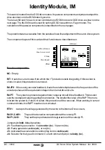
On the identity card, put selector J1 in the (bc) position.
Fagor supplies these full connections (cable + connectors), SEC and DCEC.
Tacho feedback connection.
The tacho must turn with the motor shaft and it must not be mounted anywhere else in the
transmission chain.
On the identity card, put selector J1 in the (de) position.
Fagor supplies this full connection (cable + connectors), DCTC.
DC Servodrive
DC Motor
Clockwise Rotation
at Shaft End. CWR.
G
8
9
CONTROL
SIGNALS
CONNECTOR
DC Motor
Top view.
9
T
8
Ready Made Cable
DCTC 2x0.34
Ch.
Ch.
+5V
E
N
CO
DE
R
IN
P
U
T
E
N
CO
DE
R
OU
T
P
U
T
(HD,Sub-D,F15)
1
5
11
15
(HD,Sub-D,M15)
1
5
11
15
(HD,Sub-D,M15)
6
5
4
3
2
1
15
9
*A
B
*B
Z
*Z
0V
A
11
DC Servodrive
DC Motor
Front View
TT
L
E
n
c
o
d
e
r
Ready Made Cable
DCEC 5/10/15/20
9
8
7
6
5
4
3
2
1
6
5
4
3
2
1
7
8
9
ROC 9
Blue
Grey
Green
Brown
Pink
Black
Yellow
Red
1
2
3
4
A
*A
B
*B
5
6
7
8
Z
*Z
11
0 V
(HD, Sub-D, F15)
Ready Made Cable
SEC 1/3/5/10/15/20
1
2
3
4
5
6
7
8
11
(Sub-D, M15)
8
1
15
9
(Sub-D,
F15)
Green
Yellow
Blue
Purple
Grey
Pink
Brown
White
Black
Fa
go
r C
N
C
C
a
b
le 4
x
2x
0,
1
4
+
2
x0
,5
(Length in meters;
including connectors)