background image

Hardware configuration.  

CNC 8070

CENTRAL U

N

IT 

FOR C

ABI

NET (Q7-A

 PLATFORM).

7.

·137·

(R

EF

: 1911)


7

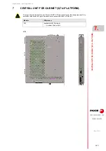
CENTRAL UNIT FOR CABINET (Q7-A PLATFORM). 

Do not get into the inside of the unit. This unit MUST NOT be opened by unauthorized personnel. Only
personnel authorized by Fagor Automation may access the interior of this unit.

Module.

Differences.

U70

Available for 8070 models.

• In-cabinet Central Unit

U70

Summary of Contents for CNC 8070

Page 1: ...Ref 1911 8070 CNC Hardware configuration...

Page 2: ...to the user to keep the unit virus free in order to guarantee its proper operation Computer viruses at the CNC may cause it to malfunction FAGOR AUTOMATION shall not be held responsible for any perso...

Page 3: ...ETX PLATFORM 3 1 Heat dissipation models 41 CHAPTER 4 CENTRAL UNIT CPU ENCLOSURE Q7 A PLATFORM 4 1 Calculation of the surface needed for heat dissipation 45 CHAPTER 5 CENTRAL UNIT MONITOR ETX PLATFORM...

Page 4: ...st over voltage and reverse voltage 103 6 4 3 Voltage supply at 24 V DC 103 6 4 4 Power supply via UPS 104 6 4 5 Ground connection 104 6 4 6 Power supply requirements 104 6 4 7 NOT recommended circuit...

Page 5: ...e 180 8 5 Elements connectors 181 8 6 Overall connection 183 CHAPTER 9 MONITOR 21 MULTITOUCH 9 1 Specifications 186 9 2 General diagram 187 9 3 Dimensions 188 9 4 Enclosure and mounting of the module...

Page 6: ...the keyboard distribution 235 12 8 Using the Fagor logo key 237 12 9 Numeric keypad 237 12 10 Touchpad touch screen 238 CHAPTER 13 OP PANEL OP PANEL SPDL RATE 13 1 Specifications 239 13 2 General dia...

Page 7: ...he CNC 265 17 2 Configuring the Thin Client 267 17 2 1 Configure the network protocol for network or point to point connection 267 17 2 2 Configure the communication between the CNC and the Thin Clien...

Page 8: ...BLANK PAGE 8...

Page 9: ...ntegrated PLC PLC execution time Digital inputs Digital outputs Marks Registers Timers Counters Symbols 1ms K 1024 1024 8192 1024 512 256 Unlimited Block processing time 1 ms 1 ms Remote modules RIOW...

Page 10: ...art from machining a part This feature must be active when installing this type of application even if they are Office files Once the application has been installed it is recommended to close the CNC...

Page 11: ...uch as the aerospace industry machining demands mean that classic compensation tools are becoming suboptimal Volumetric compensation FVC comes in to complement the machine adjusting tools When mapping...

Page 12: ...CNC creates a program During manual nesting the operator distributes the parts on top of the sheet material SOFT AUTO NESTING Automatic nesting Nestingconsistsofcreatingapatternonthesheetmaterial usi...

Page 13: ...rmity for the CNC is available in the downloads section of FAGOR S corporate website http www fagorautomation com Type of file Declaration of conformity WARRANTY TERMS The warranty conditions for the...

Page 14: ...BLANK PAGE 14...

Page 15: ...it 15 passive screen Corrected the numbering of the pinout of Phoenix Contact connectors The handwheel module with the E stop button has been removed from the manual Corrected mouse dimensions The PC1...

Page 16: ...oard VERTICAL KEYB New keyboard HORIZONTAL KEYB New operator panel OP PANEL Hardware The LCD 10 model has been eliminated The LCD 10K model front mounting has been eliminated The LCD 15 model front mo...

Page 17: ...ZONTAL KEYB 2 0 TOUCHPAD New C70 15AT model New C70 15A model Model C70 15 DISCONTINUED Model C70 15T DISCONTINUED Model C70 15A DISCONTINUED Model C70 15 available again Corrected the resolution of t...

Page 18: ...BLANK PAGE 18...

Page 19: ...t handle the connectors with the unit connected to AC power Before handling these connectors I O feedback etc make sure that the unit is not powered Interconnection of modules Use the connection cable...

Page 20: ...relay coils contactors motors etc uncoupled Use the proper power supply Use an external regulated 24 Vdc power supply for the keyboard operator panel and the remote modules Connecting the power supply...

Page 21: ...070 21 REF 1911 Symbols that the product may carry Ground symbol This symbol indicates that that point must be under voltage ESD components This symbol identifies the cards as ESD components sensitive...

Page 22: ...BLANK PAGE 22...

Page 23: ...0 Kg 375 lb 2 Attach a label to the device indicating the owner of the device along with contact information address telephone number email name of the person to contact type of device serial number e...

Page 24: ...BLANK PAGE 24...

Page 25: ...pressure to clean the unit because it could cause the accumulation of electrostatic charges that could result in electrostatic shocks The plastics used on the front panel are resistant to grease and...

Page 26: ...BLANK PAGE 26...

Page 27: ...he machine that integrates this CNC meets the 89 392 CEE directive Safety conditions In order to avoid personal injuries and damage to this product or to those connected to it read carefully the secti...

Page 28: ...Hardware configuration CNC 8070 1 PREVIOUS INFORMATION 28 REF 1911...

Page 29: ...ntral unit ETX platform Identification Description U65 In cabinet Central Unit Connecting to a DVI D monitor Connecting to keyboards and operator panels via the CAN Connecting to keyboards via the USB...

Page 30: ...n colors Resolution 1920 1080 Identification Description C70 15 C70 15T discontinued The central unit is located on the rear of the monitor 15 1024 768 pixels monitor aspect ratio 4 3 24 bit color USB...

Page 31: ...m 16 54 16 configurable user keys Jog switch 0 200 15 configurable jog keys CNC power down key CAN communication CANopen protocol Spindle override key Possibility to connect up to three handwheels OP...

Page 32: ...platform only Identification Description HORIZONTAL KEYB CAN horizontal alphanumeric QWERTY keyboard VERTICAL KEYB CAN vertical alphanumeric keyboard Identification Description HORIZONTAL KEYB MOUSE...

Page 33: ...n RIO5 series CAN communication CANopen protocol Digital inputs and outputs Analog inputs and outputs Analog inputs for PT100 temperature sensors RIOW series CAN communication CANopen protocol Digital...

Page 34: ...binet 2 12 EtherCAT remote modules only Q7 A platform Remote modules may be used to have extra resources distributed at different locations of the machine or installed in the electrical cabinet Identi...

Page 35: ...ts that make up the CNC system CAN CNC Operator panel Remote modules Servo drive system RCS S Modules Sercos II DDS VGA Keyboard C70 10K Sercos II HORIZONTAL KEYB 2 0 TOUCHPAD RCS S RIOW RIO5 RIOR CAN...

Page 36: ...hematic description of all the elements that make up the CNC system CNC Operator panel Remote modules RCS S Modules USB EtherCAT Keyboard MONITOR LCD 10K 001 HORIZONTAL KEYB 2 0 TOUCHPAD RCS S RIOW RI...

Page 37: ...hematic description of all the elements that make up the CNC system U70 CNC Servo drive system RCS S Modules USB DDS EtherCAT Keyboard HORIZONTAL KEYB 2 0 TOUCHPAD RCS S Sercos II Remote modules RIOW...

Page 38: ...Hardware configuration CNC 8070 2 CONFIGURATION General diagram for U60 Q7 A platform 38 REF 1911...

Page 39: ...ove heat dissipation Minimum gaps recommended between the enclosure walls and the central unit To ensure that it does not exceed this temperature respect the recommended minimum gap between the sides...

Page 40: ...o be considered when calculating the total surface Power dissipated by the CNC To calculate the dissipated power all the elements that are inside the enclosure must be taken into account Data Units Me...

Page 41: ...h internal fan Fan whose air flow Q 13 6 m h facing down Fan whose air flow Q 13 6 m h facing up Fan whose air flow Q 30 m h facing down Unpainted surface Surface with smooth metallic enamel A P 5 T A...

Page 42: ...re For this case the volume of air flow is calculated necessary to evacuate the heat generated inside the enclosure The fan s air flow is calculated according to the power dissipated by the CNC and th...

Page 43: ...s and the central unit to let the air flow and improve heat dissipation Minimum enclosure dimensions Ifnecessary increasethedimensionsoftheenclosure NEVERusesmallerdimensionsthan the recommended minim...

Page 44: ...U ENCLOSURE Q7 A PLATFORM 44 REF 1911 Characteristics of the inside fan of the enclosure Type of fan ball bearings Work temperature between 10 C 14 F and 60 C 140 F Air flow greater than 13 6 m h Life...

Page 45: ...pation by making the air flow inside Data Units Meaning TO m Total required surface The entire surface of the enclosure except the bottom one is considered useful P W Total power dissipated by all the...

Page 46: ...Hardware configuration CNC 8070 4 CENTRAL UNIT CPU ENCLOSURE Q7 A PLATFORM Calculation of the surface needed for heat dissipation 46 REF 1911...

Page 47: ...a cover Module Differences C70 15 15 1024 768 pixels monitor aspect ratio 4 3 24 bit color C70 15T discontinued 15 1024 768 pixels monitor aspect ratio 4 3 24 bit color Touch screen C70 15AT 15 1920...

Page 48: ...MONITOR ETX PLATFORM In cabinet model 48 REF 1911 5 2 In cabinet model Available for 8065 and 8065 Power models Module Differences U70 In cabinet Central Unit Connecting to a VGA monitor Connecting to...

Page 49: ...ttery CMOS battery accessible from the outside CR2450 CN371 depending on the CNC model Choice of OS image Windows7A C70 15AT multi touch Windows7 C70 10K C70 15AT single touch WindowsXP C70 10K C70 15...

Page 50: ...ion Digital outputs 24 V DC 500 mA ON cycle minimum 75 s 25 s optional in two of them 2 feedback inputs 5 V 0 250 A Incremental differential TTL or differential TTL signal Frequency 100 kHz TTL 1000 k...

Page 51: ...n CNC 8070 CENTRAL UNIT MONITOR ETX PLATFORM 5 Dimensions 51 REF 1911 5 4 Dimensions 5 4 1 U70 mm inch Da 45 1 77 Db 234 3 9 22 mm inch a 254 10 00 b 250 3 9 85 c 90 3 54 d 208 3 8 20 Ra R 3 50 R 0 14...

Page 52: ...uration CNC 8070 5 CENTRAL UNIT MONITOR ETX PLATFORM Dimensions 52 REF 1911 5 4 2 U70 M mm inch Da 45 1 77 Db 234 3 9 22 mm inch a 254 10 00 b 250 3 9 85 c 132 5 20 d 208 3 8 20 Ra R 3 50 R 0 14 a b c...

Page 53: ...Hardware configuration CNC 8070 CENTRAL UNIT MONITOR ETX PLATFORM 5 Dimensions 53 REF 1911 5 4 3 C70 10K mm inch Da 389 15 31 Db 319 12 56 mm inch a 420 16 54 b 350 13 78 c 126 4 96 a b Db c Da...

Page 54: ...Hardware configuration CNC 8070 5 CENTRAL UNIT MONITOR ETX PLATFORM Dimensions 54 REF 1911 5 4 4 C70 15 mm inch a 420 16 54 b 350 13 78 c 124 4 88 mm inch Da 389 15 31 Db 319 12 56 Da Db a b c...

Page 55: ...dware configuration CNC 8070 CENTRAL UNIT MONITOR ETX PLATFORM 5 Dimensions 55 REF 1911 5 4 5 C70 15T DISCONTINUED mm inch a 420 16 54 b 350 13 78 c 124 4 88 mm inch Da 389 15 31 Db 319 12 56 Da Db a...

Page 56: ...ware configuration CNC 8070 5 CENTRAL UNIT MONITOR ETX PLATFORM Dimensions 56 REF 1911 5 4 6 C70 15AT mm inch a 420 16 54 b 350 13 78 c 114 4 48 d 124 4 88 mm inch Da 391 15 40 Db 321 12 63 Da Db a b...

Page 57: ...space that allows the cables to be connected respecting their radius of curvature Special care must be taken with the Sercos connection because bending the optic fiber too much could break it Keep th...

Page 58: ...43 H 322 12 67 Minimum recommended distance mm inch D 174 6 85 e 1 5 4 0 0 06 0 16 H W D e Even though the size of the cut out for the C70 15AT model is mechanically compatible with models C70 15 and...

Page 59: ...rt the unit into the enclosure it must have a big enough hole to allow to insert it easily without obstacles and without forcing the unit The module is secured from the inside of the enclosure therefo...

Page 60: ...not one must know the power dissipated by each one of its modules 5 6 2 Cabinet design When attaching the module the following requirements must be met Place the modules in a vertical position To secu...

Page 61: ...nfiguration CNC 8070 CENTRAL UNIT MONITOR ETX PLATFORM 5 Power supply for the module 61 REF 1911 5 7 Power supply for the module Power supply Battery LATCH button and red status LED Over voltage prote...

Page 62: ...agor battery to turn off the equipment in a controlled manner during a power outage The battery provides an autonomy of about 20 minutes when it is fully charged Connector pinout Plug in part 3 pole P...

Page 63: ...y be accessed from the outside to protect against over voltage greater than 36 V DC or 25 V AC The central unit is also protected against reverse connection of the power supply preventing it from star...

Page 64: ...tors 64 REF 1911 5 8 Hardware functionality Connectors 5 8 1 Front of the monitor USB connector USB 2 0 port accessible from the front and protected by a cover for the connection of a pendrive mouse o...

Page 65: ...2 Central unit Peripheral board VGA IOIOI PROBE 1 2 VGA connector Connection to an off the shelf VGA monitor Emergency relay Relay for the emergency chain PROBE connector Connection of 2 probes Seria...

Page 66: ...ected to network Yellow The LED blinks when data is being transferred Pin Signal 1 5 V 2 DT 3 DT 4 GND 4 2 3 1 4 2 3 1 No USB devices must be used nor connected while executing a part program Using US...

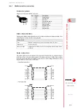
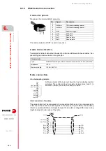
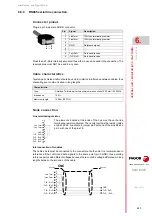
Page 67: ...wered up and running properly they open again when the CNC is turned off or when an internal failure occurs These relays withstand up to 1A at 24V Pin RS232 signal RS422 signal RS485 signal 1 DCD 2 Rx...

Page 68: ...LED s Switch to activate the line termination resistor of the CAN bus and bus status indicating LED s CAN bus CAN connector CAN bus connection Local digital inputs and outputs The left connector has 8...

Page 69: ...e blinking frequency Bus used to communicate with drives Sercos II bus IN OUT connectors Sercos emitter and receiver See 5 12 7 Sercos II bus on page 89 Type of blinking Meaning LED off The module wor...

Page 70: ...onnector must be connected to 24 V DC and GND Machine parameter NLOCOUT indicates the number of digital outputs available at the connector the rest of the pins will act as digital inputs Refer to the...

Page 71: ...BATTERY connector Connecting the emergency battery for voltage supply and charging it Ground connection Auxiliary 24 V DC output Auxiliary 24V output to supply the operator panel Protection fuse Fuse...

Page 72: ...is integrated into the monitor LCD 10K or close to it BATTERY connector Battery voltage and charge 5 pin male Phoenix contact minicombicon connector 3 5 mm pitch This connector can also be used to co...

Page 73: ...only for the MCU model Electrical characteristics of the PCI expansion Characteristic Description Board size Half Size Connector PCI 5 V Interface PCI 32 bit 33 MHz Power supply 5 V 2 A 3 3 V 2 5 A Bo...

Page 74: ...AL UNIT MONITOR ETX PLATFORM Hardware functionality Connectors 74 REF 1911 Jumper JP1 Voltage selector V I O 3 pin jumper for selecting the voltage of V I O JP1 Selected voltage 5 V 3 3 V 5 V V I O 3...

Page 75: ...be connected to a digital input and may be managed from the PLC using the NEXTMPGAXIS mark X11 Handwheel Handwheel connection Rear view Pin Signal Function 1 5 V Power supply 2 3 4 MPG3 B B signal of...

Page 76: ...stics Characteristic Value Nominal voltage 24 V DC between 18 V DC and 30 V DC High threshold 1 Over 18 V DC Low threshold 0 Under 9 V DC Typical consumption of each input 5 mA Maximum consumption of...

Page 77: ...signal Characteristic Value 5 V power consumption 250 mA for each input Characteristic Value Maximum frequency 100 kHz Phase difference 90 20 High threshold logic level 1 VIH 2 2 V VIH 5 V Low thresh...

Page 78: ...er 3 Remove the battery by pulling it up smoothly 4 Insert the new battery maintaining the same polarity The battery must get into its housing easily without having to force it 5 Put the protective co...

Page 79: ...ard only at its corners or edges do not touch its components contacts or conducting lines Voltage for the pins V I O The supply voltage for the V I O pins of the connector may be set for 5V or 3 3V by...

Page 80: ...the board into the PCI expansion only in MCU models 80 REF 1911 Secure the board with the screw F Tuurn and fasten the locking angle bracket G to hold the board Put and slide the lid in the direction...

Page 81: ...use pins 1 and 6 to 9 Probe whose output has a normally open contact Connection to 5 V The connection acts upon the up flank positive pulse of the probe signal Probe whose output has a normally open c...

Page 82: ...l Interface with an open collector output Connection to 5 V The connection acts upon the down flank negative pulse of the probe signal Interface with an open collector output Connection to 24 V The co...

Page 83: ...8070 CENTRAL UNIT MONITOR ETX PLATFORM 5 Connections 83 REF 1911 Interface with a PUSH PULL output Connection to 24 V Depending on the interface being used the connection acts upon the up flank or dow...

Page 84: ...nt voltages because there could be voltage differences in long lengths between the two ends of the cable Characteristic Type Shielded Twisted pair with a minimum wire section of 0 14 mm Capacitance 16...

Page 85: ...iding reference points with different voltages because there could be voltage differences in long lengths between the two ends of the cable Characteristic Type Shielded Twisted pair with a minimum wir...

Page 86: ...oints with different voltages because there could be voltage differences in long lengths between the two ends of the cable Characteristic Type Shielded Twisted pair with a minimum wire section of 0 20...

Page 87: ...at each end The unshielded portion of the wires of an unshielded cable cannot be longer than 75 mm Pin 15 is offered for compatibility We recommend to connect the cable shield to the connector housin...

Page 88: ...t 10 MHz Use a cable having the recommended characteristics to ensure a transmission at 100 MHz Even so since the transmission speed depends on the configuration of the network number of nodes their c...

Page 89: ...on length and dynamic and static installation characteristics Fiber optic cable with polymer core SFO SFO FLEX for up to 40 meters If the fiber opticcableisgoingtowithstanddynamicconditions moving alw...

Page 90: ...change at the Address switch to be assumed the corresponding drive must be reset and the CNC powered off and back on The fact that the drive identified with number 1 for example corresponds to the X a...

Page 91: ...channels Cyclic channel fast The data is transmitted in everyposition loop It contains the commands feedback etc Each variable read or written at the drive is included in this information package In o...

Page 92: ...imum length of the cable between elements is 0 3m 1 ft in Mlink I mode and 0 5 m 1 7 ft in Mlink II mode Twisted pair shielded cable should be used to minimize interference between cables thus prevent...

Page 93: ...odel Differences C70 10K Compact CNC monitor central unit keyboard and operator panel 10 4 800 600 pixels monitor aspect ratio 4 3 18 bit color C70 15 Modular CNC monitor and central unit 15 1024 768...

Page 94: ...Hardware configuration CNC 8070 6 CENTRAL UNIT MONITOR Q7 A PLATFORM 94 REF 1911 C70 15AT...

Page 95: ...4 4 8070 L select CP IC E352 2 2 CP IC E354 4 4 RAM 2 GB Non volatile RAM FRAM Storage select SO CNC and user programs Internal 4 GB NandFlash Internal 8 GB NandFlash Storage expansion optional addit...

Page 96: ...a cover 1 USB 3 0 port 1 RS 232 422 485 115 kbps serial port optional 1 Ethernet port for 10 100 1000 BaseT connection CAN Bus CANfagor CANopen Sercos II bus EtherCAT bus Inputs outputs 16 opto couple...

Page 97: ...ware configuration CNC 8070 CENTRAL UNIT MONITOR Q7 A PLATFORM 6 Dimensions 97 REF 1911 6 2 Dimensions 6 2 1 C70 10K mm inch Da 388 15 28 Db 318 12 52 mm inch a 420 16 54 b 350 13 78 c 68 2 68 a b Db...

Page 98: ...Hardware configuration CNC 8070 6 CENTRAL UNIT MONITOR Q7 A PLATFORM Dimensions 98 REF 1911 6 2 2 C70 15 mm inch a 420 16 54 b 350 13 78 c 68 2 68 mm inch Da 389 15 31 Db 319 12 56 Da Db a b c...

Page 99: ...Hardware configuration CNC 8070 CENTRAL UNIT MONITOR Q7 A PLATFORM 6 Dimensions 99 REF 1911 6 2 3 C70 15AT mm inch a 420 16 54 b 350 13 78 c 63 2 48 mm inch Da 391 15 40 Db 321 12 63 Da Db a b c...

Page 100: ...r flow and improve heat dissipation In the connector area reserve a space that allows the cables to be connected respecting their radius of curvature Special care must be taken with the Sercos connect...

Page 101: ...C70 15 C70 15AT mm inch W 392 15 43 H 322 12 67 mm inch e 1 5 4 0 0 06 0 16 H W e Even though the size of the cut out for the C70 15AT model is physically compatible with the C70 15 and C70 15T models...

Page 102: ...he unit into the enclosure it must have a big enough hole to allow to insert it easily without obstacles and without forcing the unit The module is secured from the inside of the enclosure therefore t...

Page 103: ...accessed from the outside to protect against over voltage greater than 36 V DC or 25 V AC The central unit is also protected against reverse connection of the power supply 6 4 3 Voltage supply at 24...

Page 104: ...ripple and noise Output current A ThecontinuousloadcurrentmustbegreaterthanthecurrentconsumedbytheCNC 2 A at the maximum temperature inside the electrical cabinet enclosure where the power supply is...

Page 105: ...ircuits usearegulatedsecond phasetopowerdeviceswithlarge load fluctuations so as not to affect the CNC and other units Example 1 Not recommended diagram A rectifier circuit is a circuit that uses diod...

Page 106: ...saves the position of the axes the rest of the data that it saves is determined by machine parameters like for example PLC registers parameter BKUPREG common arithmetic parameters parameter BKUPCUP et...

Page 107: ...9 E21 Local feedback input See Page 109 E36 Handwheel input only C70 10K model See Page 109 F2A Protection fuse See Page 110 H30A H30B USB A 2 0 Ports See Page 110 H30C USB A 3 0 Ports See Page 110 H3...

Page 108: ...ch 3 5 mm Connection technique Screw connection Minimum maximum tightening torque 0 22 0 25 Nm Minimum maximum section 0 14 1 5 mm Minimum maximum AWG section 28 16 Rated current In 8 A Cable data Len...

Page 109: ...ee 6 8 10 EtherCAT bus on page 128 Plug in part 15 pin female SUB D HD connector Connect the cable shield to the connector housing at both ends Pin Signal Function 1 A Feedback signals 2 A 3 B 4 B 5 I...

Page 110: ...kind of hub to the USB port Type A USB 3 0 connector Pin Signal 1 5 V 2 DT 3 DT 4 GND 5 StdA_SSRX 6 StdA_SSRX 7 GND_DRAIN 8 StdA_SSTX 9 StdA_SSTX Do not run part programs from a USB device whether it...

Page 111: ...to day writing Fagor Automation shall not be held responsible for any problems caused by using lower quality CFast cards Connector data Number of poles 9 Pitch 2 5 mm Connection technique Spring conn...

Page 112: ...hing 4 5 LO3 LO4 Local digital outputs 6 GND 0 V reference signal Pin Signal Function 1 24 V 24 V DC voltage supply 2 5 LO5 LO8 Local digital outputs 6 GND 0 V reference signal For the PWM and synchro...

Page 113: ...h to be stripped 10 mm See 6 8 2 Connecting the relay for the emergency chain on page 118 Connector data Number of poles 3 Pitch 3 5 mm Connection technique Spring connection Minimum maximum section 0...

Page 114: ...serial line available soon Thetypeofseriallineisselectedbymeansofthemachineparameters parameterRSTYPE Plug in part 9 pin male SUB D connector Pin RS232 signal RS422 signal RS485 signal 1 DCD 2 RxD Lin...

Page 115: ...log outputs have the following characteristics Characteristic Value Nominal voltage 24 V DC between 18 V DC and 30 V DC Activation level From 11 V DC on and between 2 1 mA and 2 6 mA Deactivation leve...

Page 116: ...erential TTL signal Characteristic Value 5 V power consumption 250 mA Characteristic Value Maximum frequency 100 kHz Phase difference 90 20 High threshold logic level 1 VIH 2 2 V VIH 5 V Low threshold...

Page 117: ...F 1911 Work levels for sinusoidal 1 Vpp signal Characteristic Value Maximum frequency 500 kHz A and B signals Amplitude 0 6 1 2 Vpp A and B signals Centered V1 V2 2 Vpp 6 5 A and B signals Ratio VApp...

Page 118: ...forwhenaninternalfailureoccurs The relay withstands up to 1 A at 24 V Connector pinout Plug in part 2 pole Phoenix contact minicombicon connector 3 5 mm pitch Do not handle the connectors while the CN...

Page 119: ...nected to the metallic hood at each end The unshielded portion of the wires of an unshielded cable cannot be longer than 75 mm Plug in part 15 pin male SUB D HD type connector Connect the cable shield...

Page 120: ...s of the machine Connector pinout 10 pin male Phoenix contact minicombicon connector 3 5 mm pitch Cable characteristics The cable being used must have overall shield The unshielded portion of the wire...

Page 121: ...ee The wires of the shielded cable must not be longer than 75 mm without the protection shield Probe connection Probe whose output has a normally open contact Connection to 5 V The connection acts upo...

Page 122: ...al Interface with an open collector output Connection to 5 V The connection acts upon the down flank negative pulse of the probe signal Interface with an open collector output Connection to 24 V The c...

Page 123: ...070 CENTRAL UNIT MONITOR Q7 A PLATFORM 6 Connections 123 REF 1911 Interface with a PUSH PULL output Connection to 24 V Depending on the interface being used the connection acts upon the up flank or do...

Page 124: ...MHz Use a cable having the recommended characteristics to ensure a transmission at 100 MHz or 1000 MHz Even so since the transmission speed depends on the configuration of the network number of nodes...

Page 125: ...voltages because there could be voltage differences in long lengths between the two ends of the cable Characteristic Type Shielded Twisted pair with a minimum wire section of 0 14 mm Capacitance 164 p...

Page 126: ...reference points with different voltages because there could be voltage differences in long lengths between the two ends of the cable Characteristic Type Shielded Twisted pair with a minimum wire sec...

Page 127: ...avoiding reference points with different voltages because there could be voltage differences in long lengths between the two ends of the cable Characteristic Type Shielded Twisted pair with a minimum...

Page 128: ...n the bus Connector Cable characteristics Fagor Automation supplies the required cables for EtherCAT communication when using third party cables these must be of the same category as those supplied by...

Page 129: ...urator KPA EtherCAT Studio by Koening pa GmbH under license which can operate both online and offline to define the bus topology and create the ENI file containing the bus device information This file...

Page 130: ...puts and outputs are mapped to PLC registers Fagor has the Fagor EtherCAT Mapper program to carry out the mapping From the ENI file generated by the EtherCAT configurator this program makes a mapping...

Page 131: ...ield may be connected to either one Characteristics of the CAN cable Use a specific CAN cable The ends of all the wires and the shield must be protected by the corresponding terminal pin Also use the...

Page 132: ...rm 0 ISO GND CAN L SHIELD CAN H SHIELD ISO GND CAN L SHIELD CAN H SHIELD 4 0 F D C B 9 8 7 5 3 1 1 MODULE 1 0 ADDRESS 1 Line Term 0 CNC ISO GND CAN L SHIELD CAN H SHIELD 4 0 F D C B 9 8 7 5 3 1 1 MODU...

Page 133: ...e following approximate values Assigning other values may cause communication errors due to signal distortion Selecting the speed for the CANopen bus WhenusingtheCANopenprotocol thetransmissionspeedat...

Page 134: ...leisgoingtowithstanddynamic conditions moving alwaysusetheSFO FLEX cable If the cable will be subject to static conditions it will not be moving the SFO cable will be enough Fiber optic cable with gla...

Page 135: ...ple corresponds to the X axis to Y or to another one is irrelevant However it is a good idea for clarity sake that the machine axes X Y Z U V W A B and C be assigned consecutive numbers in that order...

Page 136: ...smissions there must be two separate transmission channels Cyclic channel fast The data is transmitted in every position loop It contains the commands feedback etc Each variable read or written at the...

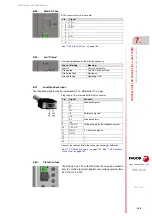
Page 137: ...NTRAL UNIT FOR CABINET Q7 A PLATFORM Do not get into the inside of the unit This unit MUST NOT be opened by unauthorized personnel Only personnel authorized by Fagor Automation may access the interior...

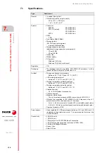
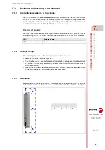
Page 138: ...ween 40 C 40 F and 70 C 158 F CNC working temperature Between 5 C 41 F and 55 C 131 F Working temperature outside the cabinet Between 5 C 41 F and 40 C 104 F Working temperature inside the cabinet Bet...

Page 139: ...TTL 1000 kHz TTL differential 500 kHz 1 Vpp 1 relay with one normally open contact 1A at 24V 2 probe inputs 5 V or 24 V 1 entry for UPS unit control Type Description To help increase storage space Fag...

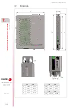
Page 140: ...8070 7 CENTRAL UNIT FOR CABINET Q7 A PLATFORM Dimensions 140 REF 1911 7 2 Dimensions mm inch a 235 5 9 27 b 313 1 12 32 c 36 5 1 43 d 284 11 18 mm inch Da 16 5 0 65 Db 301 5 11 87 mm inch Ra R 2 25 R...

Page 141: ...her the electrical cabinet needs external cooling or not one must know the power dissipated by each one of its modules 7 3 2 Cabinet design When attaching the module the following requirements must be...

Page 142: ...se that may be accessed from the outside to protect against over voltage greater than 36 V DC or 25 V AC The central unit is also protected against reverse connection of the power supply 7 4 3 Voltage...

Page 143: ...ple and noise Output current The continuous load current must be greater than the current consumed by the CNC 2 A at the maximum temperature inside the electrical cabinet enclosure where the power sup...

Page 144: ...ecircuits usearegulatedsecond phasetopowerdeviceswithlarge load fluctuations so as not to affect the CNC and other units Example 1 Not recommended diagram A rectifier circuit is a circuit that uses di...

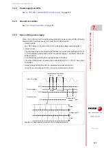
Page 145: ...CNC has non volatile RAM FRAM that keeps the information saved in it even when a power failure occurs The non volatile RAM FRAM always saves the position of the axes the rest of the data that it save...

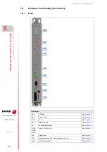
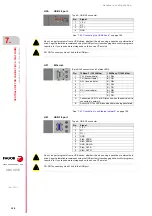
Page 146: ...nt H66 H30 B32 B28 E21 I26 I25 D63 B64 Connector B28 CAN bus See Page 148 B32 Sercos II bus See Page 148 D63 Led See Page 149 B64 EtherCAT bus See Page 149 E21 Local feedback input See Page 149 H30A H...

Page 147: ...B 2 0 port See Page 150 H31A Ethernet See Page 150 H61 Type A USB 3 0 port See Page 150 H62 CFast See Page 151 Ground connection I23 X27 A22 I65 F2A I24 Connector A22 24 V supply input See Page 148 F2...

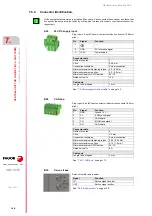
Page 148: ...A Cable data Length to be stripped 7 mm See 7 4 Power supply for the module on page 142 Connector data Number of poles 5 Pitch 3 5 mm Connection technique Screw connection Minimum maximum tightening...

Page 149: ...greater than 36 V DC or 25 V AC RJ45 connectors for 4 wire cable Pin Signal 1 TD 2 TD 3 RD 4 5 6 RD 7 8 See 7 8 8 EtherCAT bus on page 166 Its meaning depends on the blinking frequency Type of blinkin...

Page 150: ...Ethernet network on page 165 8 pin RJ45 connector and 2 status LED s Pin 10Base T 10 100 Mhz 1000Base T 1000 Mhz 1 TX transmit data BI_DA 2 TX transmit data BI_DA 3 RX receive data BI_DB 4 BI_DC 5 BI_...

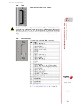
Page 151: ...lower quality CFast cards See 7 8 3 Connecting the DVI D video output on page 160 DVI D video output Maximun resolution of 1920 1200 Pin Se al 1 TMDS 2 Red Link 1 2 TMDS 2 Red Link 1 3 TMDS 2 4 SHIELD...

Page 152: ...G section 26 20 Rated current In 4 A Cable data Length to be stripped 8 mm See 7 7 1 Digital inputs on page 156 Left connector Pin 1 coded Right connector Pin 9 coded Plug in part Two coded connectors...

Page 153: ...1 coded Right connector Pin 6 coded Plug in part Two coded connectors 6 pole Phoenix contact minicombicon connector 2 5 mm pitch Left connector Pin 1 coded Right connector Pin 6 coded Both connectors...

Page 154: ...tch 3 5 mm Connection technique Screw connection Minimum maximum tightening torque 0 22 0 25 Nm Minimum maximum section 0 14 1 5 mm Minimum maximum AWG section 28 16 Rated current In 8 A Cable data Le...

Page 155: ...n on page 160 Connector data Number of poles 3 Pitch 3 5 mm Connection technique Spring connection Minimum maximum section 0 2 1 5 mm Minimum maximum AWG section 24 16 Rated current In 8 A Cable data...

Page 156: ...ts Use shielded cables connecting their meshes to the corresponding shield pin All the analog outputs have the following characteristics Characteristic Value Nominal voltage 24 V DC between 18 V DC an...

Page 157: ...s for differential TTL signal Characteristic Value 5 V power consumption 250 mA Characteristic Value Maximum frequency 100 kHz Phase difference 90 20 High threshold logic level 1 VIH 2 2 V VIH 5 V Low...

Page 158: ...REF 1911 Work levels for sinusoidal 1 Vpp signal Characteristic Value Maximum frequency 500 kHz A and B signals Amplitude 0 6 1 2 Vpp A and B signals Centered V1 V2 2 Vpp 6 5 A and B signals Ratio VAp...

Page 159: ...ed before handling the connectors Do not make any connections while the CNC is powered Disconnect the power before making a connection It is up to the system integrator to meet all the requirements of...

Page 160: ...en the CNC is powered up and runningproperly itopensagainwhentheCNCisturnedofforwhenaninternalfailureoccurs The relay withstands up to 1 A at 24 V Connector pinout Plug in part 2 pole Phoenix contact...

Page 161: ...The cable shield must be connected to the metallic hood at each end The unshielded portion of the wires of an unshielded cable cannot be longer than 75 mm Plug in part 15 pin male SUB D HD type conne...

Page 162: ...free The wires of the shielded cable must not be longer than 75 mm without the protection shield Probe connection Probe whose output has a normally open contact Connection to 5 V The connection acts u...

Page 163: ...gnal Interface with an open collector output Connection to 5 V The connection acts upon the down flank negative pulse of the probe signal Interface with an open collector output Connection to 24 V The...

Page 164: ...0 7 CENTRAL UNIT FOR CABINET Q7 A PLATFORM Connections 164 REF 1911 Interface with a PUSH PULL output Connection to 24 V Depending on the interface being used the connection acts upon the up flank or...

Page 165: ...MHz Use a cable having the recommended characteristics to ensure a transmission at 100 MHz or 1000 MHz Even so since the transmission speed depends on the configuration of the network number of nodes...

Page 166: ...on the bus Connector Cable characteristics Fagor Automation supplies the required cables for EtherCAT communication when using third party cables these must be of the same category as those supplied...

Page 167: ...igurator KPA EtherCAT Studio by Koening pa GmbH under license which can operate both online and offline to define the bus topology and create the ENI file containing the bus device information This fi...

Page 168: ...inputs and outputs are mapped to PLC registers Fagor has the Fagor EtherCAT Mapper program to carry out the mapping From the ENI file generated by the EtherCAT configurator this program makes a mappin...

Page 169: ...ticcableisgoingtowithstanddynamicconditions moving alwaysusetheSFO FLEX cable If the cable will be subject to static conditions it will not be moving the SFO cable will be enough Fiber optic cable wit...

Page 170: ...ample corresponds to the X axis to Y or to another one is irrelevant However it is a good idea for clarity sake that the machine axes X Y Z U V W A B and C be assigned consecutive numbers in that orde...

Page 171: ...ansmissions there must be two separate transmission channels Cyclic channel fast The data is transmitted in everyposition loop It contains the commands feedback etc Each variable read or written at th...

Page 172: ...shield may be connected to either one Characteristics of the CAN cable Use a specific CAN cable The ends of all the wires and the shield must be protected by the corresponding terminal pin Also use t...

Page 173: ...HIELD ISO GND CAN L SHIELD CAN H SHIELD 4 0 F D C B 9 8 7 5 3 1 1 MODULE 1 0 ADDRESS 1 Line Term 0 CNC ISO GND CAN L SHIELD CAN H SHIELD 4 0 F D C B 9 8 7 5 3 1 1 MODULE 2 0 ADDRESS 2 ISO GND CAN L SH...

Page 174: ...ype bus requires the definition of the maximum length of the bus with parameter CANLENGTH Selecting the speed for the CANopen bus WhenusingtheCANopenprotocol thetransmissionspeedatthebusisdefinedineac...

Page 175: ...be the only one connected to the central unit for example with the central unit MCU or it may be a second monitor for example with the central unit ICU When the screen is used as a second monitor bot...

Page 176: ...of the screen to the keyboard and the VGA signal to the central unit Connect the keyboard and the operator panel to the CAN bus of the system The passive screen and the ICU central unit The passive s...

Page 177: ...g Meets EN 60068 2 32 standard Free fall packaged according to Fagor regulations 1 meter Ambient conditions Relative humidity 10 95 without condensation Work temperature 0 45 C with an average lower t...

Page 178: ...configuration CNC 8070 8 LCD 15SVGA PASSIVE MONITOR LCD15 SVGA Hardware dimensions 178 REF 1911 8 3 Hardware dimensions a c b Da Db mm inch a 420 16 54 b 350 13 78 c 61 5 2 42 mm inch Da 388 15 28 Db...

Page 179: ...while accounting for their bending radius Thecabinetmustconsidertheminimumrecommendeddistancesbetweentheenclosure walls and the hardware to let the air flow and improve heat dissipation Dimensions of...

Page 180: ...ternal support To insert the unit into the enclosure it must have a big enough hole toallowtoinsertiteasily withoutobstaclesandwithoutforcingtheunit See 8 4 1 Enclosure design on page 179 The module i...

Page 181: ...Hardware configuration CNC 8070 LCD 15SVGA PASSIVE MONITOR LCD15 SVGA 8 Elements connectors 181 REF 1911 8 5 Elements connectors Connector A Ground B VGA input C 24 V supply input D Softkeys B C D A...

Page 182: ...ctor 24 V DC voltage supply Softkeys Connection of the softkeys of the monitor to the keyboard Maximum cable length is 1 meter 1 5 6 10 11 15 Plug in part 15 pin male SUB D HD type connector Pin Signa...

Page 183: ...the connector at both ends Cable characteristics Use specific VGA cable VGA cable Flexibility Normal Type Shielded Impedance 75 Maximum length 30 m GND BLUE GREEN GND_SYNC GND_BLUE GND_GREEN GND_RED...

Page 184: ...Hardware configuration CNC 8070 8 LCD 15SVGA PASSIVE MONITOR LCD15 SVGA Overall connection 184 REF 1911...

Page 185: ...nitor to display the VGA or DVI D video signal from the central unit and also to serve as the touch screen permitting interaction with the central unit Module Description MONITOR 21W MULTITOUCH 21 5 1...

Page 186: ...ion random Degree of protection Front complies with standard IP65 Power supply Power use one of the following options 24 V DC via Phoenix type connector recommended 12 V DC via DC jack connector consu...

Page 187: ...tform Q7A platform CNC MONITOR 21W MULTITOUCH MONITOR 21W MULTITOUCH NEUTRO VGA T S USB CNC MONITOR 21W MULTITOUCH MONITOR 21W MULTITOUCH NEUTRO DVI D T S USB Connection Description VGA VGA video sign...

Page 188: ...re configuration CNC 8070 9 MONITOR 21 MULTITOUCH Dimensions 188 REF 1911 9 3 Dimensions mm inch a 558 40 21 98 b 349 80 13 77 c 40 70 1 60 d 47 70 1 88 mm inch Da 548 00 21 57 Db 339 25 13 36 Da c Db...

Page 189: ...llows the cables to be connected respecting their radius of curvature Respect the minimum distances recommended between the enclosure walls and the hardware to let the air flow and improve heat dissip...

Page 190: ...bstaclesandwithoutforcingtheunit See 9 4 1 Enclosure design on page 189 The module is mounted from inside the enclosure Once the unit has been inserted into the enclosure secure it from the inside wit...

Page 191: ...Hardware configuration CNC 8070 MONITOR 21 MULTITOUCH 9 Enclosure and mounting of the module 191 REF 1911 4 Fasten the monitor on the rear using all the fastening hooks D D 1 2 0 7 Nm...

Page 192: ...the monitor Consult Fagor Automation before using the 12 V DC option 24 V DC universal power supply Option recommended by Fagor Automation to power the monitor Power the monitor with a 24 V DC 10 1 5...

Page 193: ...al from the monitor The buttons to configure the monitor are on the back Button Description Turns the monitor on and off Automatically adjusts the clock phase horizontal position and vertical position...

Page 194: ...E F G Plug in part 9 pin female SUB D HD connector Pin Signal Function 1 DCD Data Carrier Detect 2 RxD Received Data 3 TxD Transmit Data 4 DTR Data Terminal Ready 5 GND Ground 6 DSR Data Set Ready 7 R...

Page 195: ...for the module on page 192 Plug in part 3 pole Phoenix type connector 5 08 mm pitch Rated current 16 A Pin Signal Function 1 2 GND 0 V reference signal 3 24 V Power supply 1 DC jack connector for the...

Page 196: ...2 6 DDC clock 7 DDC data 8 Not used 9 TMDS 1 Green Link 1 10 TMDS 1 Green Link 1 11 TMDS 1 3 SHIELD 12 TMDS 3 Blue Link 2 13 TMDS 3 Blue Link 2 14 5 V DC 15 GND 16 Hot plug detection 17 TMDS 0 Blue L...

Page 197: ...is valid for static installations such as cable carrying chains For further information refer to the Ordering Handbook VGA cable Type Shielded Flexibility Normal Impedance 75 Maximum length 5 m 16 40...

Page 198: ...menu The keys on the rear of the monitor have the following functionality when the OSD menu is active Button Description Main OSD menu Turns the monitor on and off OSD sub menu Turns the monitor on an...

Page 199: ...isplay menu 199 REF 1911 9 9 2 OSD menu To display the OSD menu press the MENU key on the back of the monitor Icon Description Video input Contrast Brightness Geometry for DVI input Temperature color...

Page 200: ...ss OSD sub menu Select this menu icon using the Left and Right keys and press the Menu Sel key to confirm the selection Select this menu icon using the Left and Right keys and press the Menu Sel key t...

Page 201: ...r OSD sub menu Language OSD sub menu Select this menu icon using the Left and Right keys and press the Menu Sel key to confirm the selection Select this menu icon using the Left and Right keys and pre...

Page 202: ...D sub menu Information OSD sub menu Select this menu icon using the Left and Right keys and press the Menu Sel key to confirm the selection Select this menu icon using the Left and Right keys and pres...

Page 203: ...isplay menu 203 REF 1911 Restore OSD sub menu Exit OSD sub menu Select this menu icon using the Left and Right keys and press the Menu Sel key to confirm the selection Select this menu icon using the...

Page 204: ...images of the OSD menu are property of Advantech Co Ltd Press the Left Right keys and the following message will appear on screen Do not release the keys until the screen indicates that the operation...

Page 205: ...escription HORIZONTAL KEYB CAN horizontal alphanumeric QWERTY keyboard HORIZONTAL KEYB MOUSE CAN horizontal alphanumeric QWERTY keyboard with mouse HORIZONTAL KEYB HORIZONTAL KEYB MOUSE Type Descripti...

Page 206: ...m 206 REF 1911 10 2 General diagram ETX and Q7A platforms ETX platform CNC HORIZONTAL KEYB CAN CNC HORIZONTAL KEYB CAN CNC HORIZONTAL KEYB MOUSE CAN PS 2 CNC HORIZONTAL KEYB MOUSE CAN PS 2 Connection...

Page 207: ...Hardware configuration CNC 8070 HORIZONTAL KEYB HORIZONTAL KEYB MOUSE 10 Dimensions 207 REF 1911 10 3 Dimensions mm inch a 420 16 54 b 175 6 89 c 24 0 94 mm inch Da 388 15 28 Db 143 5 63 a c b Da Db...

Page 208: ...ccounting for their bending radius Thecabinetmustconsidertheminimumrecommendeddistancesbetweentheenclosure walls and the hardware to let the air flow and improve heat dissipation Dimensions of the cut...

Page 209: ...ort To insert the unit into the enclosure it must have a big enough hole to allow to insert it easily without obstacles and without forcing the unit See 10 4 1 Enclosure design on page 208 The module...

Page 210: ...REF 1911 10 5 Power supply for the module Connector pinout 24 V DC universal power supply via Phoenix connector See 24 V DC voltage supply on page 212 24 V DC Plug in part 3 pole Phoenix type combico...

Page 211: ...ectors It is up to the system integrator to meet all the requirements of local and national electrical codes as well as all the regulations applicable regarding the grounding of the whole unit A 24 V...

Page 212: ...5 Power supply for the module on page 210 Connector data Number of poles 5 Pitch 3 5 mm Connection technique Screw connection Minimum maximum tightening torque 0 22 0 25 Nm Minimum maximum section 0...

Page 213: ...h and it depends on the total length of the bus Using the following illustrative values assigning other values may cause communication errors due to signal distortion CAN bus Line terminating resistor...

Page 214: ...ments having two CAN connectors either one may be used Once the elements have been connected define their logic order in the bus and the transmission speed General characteristics Type Shielded Twiste...

Page 215: ...nd jog panel In order for any change in the identification of the module to take effect the CNC must be restarted and turn off on the corresponding module however we recommend to change the address wh...

Page 216: ...they all must run at the same speed The speed is selected with switches 2 and 3 of the DIP switch and it depends on the total length of the bus Using the following illustrative values assigning other...

Page 217: ...supply on Module Description VERTICAL KEYB CAN vertical alphanumeric keyboard VERTICAL KEYB MOUSE CAN vertical alphanumeric keyboard with mouse VERTICAL KEYB VERTICAL KEYB MOUSE Type Description Gener...

Page 218: ...agram 218 REF 1911 11 2 General diagram ETX and Q7A platforms ETX platform CNC VERTICAL KEYB CAN CNC VERTICAL KEYB CAN CNC VERTICAL KEYB MOUSE CAN CNC VERTICAL KEYB MOUSE CAN PS 2 Connection Descripti...

Page 219: ...Hardware configuration CNC 8070 VERTICAL KEYB VERTICAL KEYB MOUSE 11 Dimensions 219 REF 1911 11 3 Dimensions mm inch a 153 6 02 b 350 13 78 c 24 0 94 mm inch Da 121 4 76 Db 318 12 52 a c b Da Db...

Page 220: ...ounting for their bending radius Thecabinetmustconsidertheminimumrecommendeddistancesbetweentheenclosure walls and the hardware to let the air flow and improve heat dissipation Dimensions of the cut o...

Page 221: ...t To insert the unit into the enclosure it must have a big enough hole to allow to insert it easily without obstacles and without forcing the unit See 11 4 1 Enclosure design on page 220 The module is...

Page 222: ...EF 1911 11 5 Power supply for the module Connector pinout 24 V DC universal power supply via Phoenix connector See 24 V DC voltage supply on page 224 24 V DC Plug in part 3 pole Phoenix type combicon...

Page 223: ...tors It is up to the system integrator to meet all the requirements of local and national electrical codes as well as all the regulations applicable regarding the grounding of the whole unit A 24 V DC...

Page 224: ...Power supply for the module on page 222 Connector data Number of poles 5 Pitch 3 5 mm Connection technique Screw connection Minimum maximum tightening torque 0 22 0 25 Nm Minimum maximum section 0 14...

Page 225: ...and it depends on the total length of the bus Using the following illustrative values assigning other values may cause communication errors due to signal distortion CAN bus Line terminating resistor L...

Page 226: ...nts having two CAN connectors either one may be used Once the elements have been connected define their logic order in the bus and the transmission speed General characteristics Type Shielded Twisted...

Page 227: ...jog panel In order for any change in the identification of the module to take effect the CNC must be restarted and turn off on the corresponding module however we recommend to change the address whil...

Page 228: ...ey all must run at the same speed The speed is selected with switches 2 and 3 of the DIP switch and it depends on the total length of the bus Using the following illustrative values assigning other va...

Page 229: ...i touch touchpad touch panel Numeric keypad optimized to operate with the CNC keys for axes feedrate speed etc Special functions with the Fagor key Keyboard distribution English United States Dimensio...

Page 230: ...the keyboard to any type of hub ETX and Q7 A platforms ETX and Q7 A platforms CNC HORIZONTAL KEYB 2 0 TOUCHPAD USB CNC PPC 21W USB HORIZONTAL KEYB 2 0 TOUCHPAD CAN ETHERNET JOG PANEL Connection Descr...

Page 231: ...rdware configuration CNC 8070 HORIZONTAL KEYB 2 0 TOUCHPAD 12 Dimensions 231 REF 1911 12 3 Dimensions mm inch a 420 16 54 b 175 6 89 c 34 1 33 d 800 31 50 mm inch Da 388 15 28 Db 143 5 63 to Da b Db c...

Page 232: ...to be connected respecting their radius of curvature Respect the minimum distances recommended between the enclosure walls and the hardware to let the air flow and improve heat dissipation Dimensions...

Page 233: ...To insert the unit into the enclosure it must have a big enough hole to allow to insert it easily without obstacles and without forcing the unit See 12 4 1 Enclosure design on page 232 The module is m...

Page 234: ...ace the cable supplied by Fagor Do not connect any type of extension cord to the USB power cable Connect the keyboard directly to the central unit do not connect the keyboard to any type of hub Charac...

Page 235: ...he keyboard distribution is not assigned to this language it is possible that the characters on screen will not match the characters of the keys In order to change the keyboard distribution the desire...

Page 236: ...n this case English United States Click on OK to finish Changing the input language Change the input language only for the active window 1 In thelanguagebar clickonthebutton Input language andselectth...

Page 237: ...is keys can be modified with the FAGOR C keys Keys Meaning 1 0 Keys F1 to F10 Key F11 Key F12 S Cancel or activate the keystroke sound T Cancel or activate the touchpad touch panel C Change the functi...

Page 238: ...one finger to simulate the double click of a mouse Tap lightly with two fingers to simulate the right click of a mouse Move the cursor Move screen pan Move screen scroll Move a finger to move the cur...

Page 239: ...up to three electronic handwheels OP PANEL SPDL RATE CAN Operator panel 420 mm 16 54 with spindle override switch Possibility to connect up to three electronic handwheels OP PANEL OP PANEL SPDL RATE T...

Page 240: ...eneral diagram 240 REF 1911 13 2 General diagram ETX and Q7A platforms ETX and Q7A platforms CNC OP PANEL OP PANEL SPDL RATE CAN CNC OP PANEL OP PANEL SPDL RATE CAN Connection Description CAN Communic...

Page 241: ...ardware configuration CNC 8070 OP PANEL OP PANEL SPDL RATE 13 Dimensions 241 REF 1911 13 3 Dimensions mm inch a 420 16 54 b 175 6 89 c 24 0 94 d 54 5 2 15 mm inch Da 388 15 28 Db 143 5 63 a c d b Da D...

Page 242: ...ting for their bending radius Thecabinetmustconsidertheminimumrecommendeddistancesbetweentheenclosure walls and the hardware to let the air flow and improve heat dissipation Dimensions of the cut off...

Page 243: ...o insert the unit into the enclosure it must have a big enough hole to allow to insert it easily without obstacles and without forcing the unit See 13 4 1 Enclosure design on page 242 The module is mo...

Page 244: ...1911 13 5 Power supply for the module Connector pinout 24 V DC universal power supply via Phoenix connector See 24 V DC voltage supply on page 246 24 V DC Plug in part 3 pole Phoenix type combicon con...

Page 245: ...to meet all the requirements of local and national electrical codes as well as all the regulations applicable regarding the grounding of the whole unit A 24 V DC voltage supply B Handwheels C CAN bus...

Page 246: ...ximum section 0 2 1 5 mm Minimum maximum AWG section 24 16 Rated current In 8 A Cable data Length to be stripped 7 mm Plug in part 3 pole Phoenix type combicon connector 7 62 mm pitch Pin Signal Funct...

Page 247: ...SH CAN shield 4 CH HIGH bus signal 5 SH CAN shield Switch 1 of the DIP switch selects the type of CAN bus DS 1 Type of CAN bus off CANfagor bus on CANopen bus When using the CANopen protocol the trans...

Page 248: ...occupy the ends of the CAN bus that is the first and last physical element in the connection The terminating elements must have the resistor activated position 1 but not the rest of the elements posi...

Page 249: ...ion of the wires of an unshielded cable cannot be longer than 75 mm Connection We recommend to run the handwheel cable as far away as possible from the power cables of the machine Plug inpart 10 poleP...

Page 250: ...having two CAN connectors either one may be used Once the elements have been connected define their logic order in the bus and the transmission speed General characteristics Type Shielded Twisted pai...

Page 251: ...panel In order for any change in the identification of the module to take effect the CNC must be restarted and turn off on the corresponding module however we recommend to change the address while th...

Page 252: ...all must run at the same speed The speed is selected with switches 2 and 3 of the DIP switch and it depends on the total length of the bus Using the following illustrative values assigning other value...

Page 253: ...E 14 1 Especificaciones M dulo Descripci n MOUSE Rat n con conector PS 2 Tipo Descripci n OP PANEL 329 General Dimensions ancho alto fondo 126 70 10 2 mm 4 96 2 76 0 40 Regulation CE Power supply Powe...

Page 254: ...Hardware configuration CNC 8070 14 MOUSE MODULE Dimensions 254 REF 1911 14 2 Dimensions mm inch a 126 4 96 b 70 2 76 c 10 2 0 40 mm inch Da 117 4 61 Db 61 2 40 4 5 0 18 a c Db Da...

Page 255: ...neral characteristics Charge time 35 hours Autonomy About 20 minutes with the battery completely charged Work temperature Between 5 C 41 F and 40 C 104 F Read the connection instructions carefully bef...

Page 256: ...ONLY ETX PLATFORM Battery dimensions 256 REF 1911 15 1 Battery dimensions a c d e b Db Da Ra Rb Dc Dd Ra mm inch a 110 4 33 b 189 3 7 45 c 60 2 36 d 21 0 83 e 147 1 5 79 mm inch Da 175 6 89 Db 8 0 31...

Page 257: ...of the battery The LED blinks while the battery is being charged and it stays on when the battery is charged Connection to the central unit Connect all the pins of the battery to the central unit The...

Page 258: ...for less than 2 seconds The CNC shows the corresponding warning and the system recovers fine Errors may occur at the CAN bus due to the lack of 24V at the remote modules If the supply is interrupted...

Page 259: ...nexpected shutdown of the CNC The UPS provides the central unit sufficient time to save data onto the FRAM and execute the shutdown sequence Read the manufacturer s instructions accompanying the produ...

Page 260: ...24 hours Output data Network operation Rated output voltage 24 V DC Output voltage range 18 V DC 30 V DC UOUT UBAT 0 5 depending on input voltage Rated output current 10 A permanent Power Boost 15 A p...

Page 261: ...the UPS 16 4 Protection fuse In order to protect the connected units the UPS is fitted with a DC fuse in the battery compartment To protect the UPS during transport and or prevent the accidental disch...

Page 262: ...d to remove the jumper Connection to the CNC and to the power supply The R1 R2 connector of the UPS is a free of potential relay Both signals can go to any DISSABLE_BAT pin of the CNC never both signa...

Page 263: ...the server and the Think Client is the client The passive screen permits having a second work station consisting of the screen itself and an operator panel OP PANEL H E Connect the operator panel to t...

Page 264: ...le must be used when connecting the Thin Client to a switch or within a local network In either case use a specific Ethernet cable In order to ensure proper performance the connection cable must be in...

Page 265: ...tart the CNC up the VNC will remain waiting and its icon will appear in the notification area of the task bar next to the clock 3 When installation is done the program shows the following option tabs...

Page 266: ...at the CNC 266 REF 1911 On the Inputs tab de select the options Accept keyboard events from clients and Accept clipboard updates from clients The option Accept pointer events from clients is only take...

Page 267: ...howsseveraltabsthat mayalsobeused toconfigure the Thin Client On the Setup Network tab select the Manually option and set the IP address e g 10 0 0 102 and the network mask e g 255 255 0 0 The network...

Page 268: ...the system in case of communication loss for some time because the Ethernet cable has been disconnected for example The purpose of the Start automatically parameter is to start the VNC client of the...

Page 269: ...e external keyboard and while starting up press the DEL key to access the BIOS The right side of the BIOS shows a menu with the instructions to browse through the BIOS Once in the BIOS select Advanced...

Page 270: ...ent Once the setup of the Thin Client is done the mouse must be disabled so the screen does not show the cursor eLux NG Apply Reset Setup Configuration Applications General Desktop Screen Mouse Keyboa...

Page 271: ...is located Electrical diagram Connecting the sensor to an analog input of the Sercos drive The example uses the first analog input of the drive pins 4 and 5 to use the second input use pins 2 and 3 C...

Page 272: ...Hardware configuration CNC 8070 18 INSTALLING A SENSOR FOR GAP CONTROL LASER MODEL 272 REF 1911...

Page 273: ...Hardware configuration CNC 8070 273 User notes REF 1911...

Page 274: ...Hardware configuration CNC 8070 274 User notes REF 1911...

Page 275: ...Hardware configuration CNC 8070 275 User notes REF 1911...

Page 276: ...Fagor Automation S Coop B San Andr s 19 Apdo 144 E 20500 Arrasate Mondrag n Spain Tel 34 943 719 200 34 943 039 800 Fax 34 943 791 712 E mail info fagorautomation es www fagorautomation com...

Reviews: