Technical Documentation
FAFNIR GmbH • Bahrenfelder Str. 19 • D-22765 Hamburg • Telephone: +49 (0)40-39 82 07-0 • Fax: +49 (0)40-3 90 63 39
10/2007Edition: 1Item No.: 207120
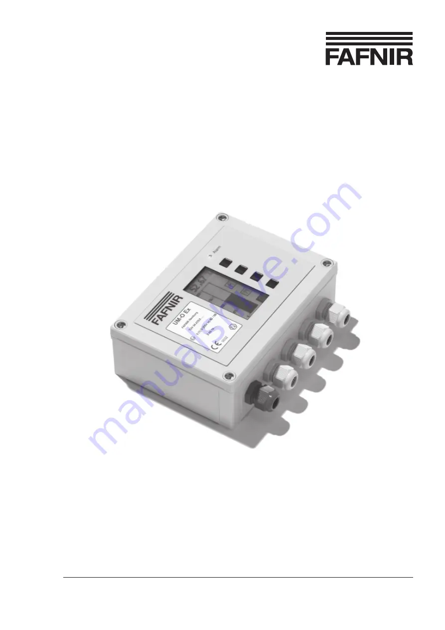
UM-X
Field display for continous level sensors
Page 1: ...echnical Documentation FAFNIR GmbH Bahrenfelder Str 19 D 22765 Hamburg Telephone 49 0 40 39 82 07 0 Fax 49 0 40 3 90 63 39 10 2007 Edition 1 Item No 207120 UM X Field display for continous level sensors ...
Page 2: ...ment analysis system 4 2 Safety instructions 5 2 1 Password 5 3 Design and operation 6 3 1 Rating plate 6 3 2 Function buttons 6 3 3 Display window 7 3 4 Alarm lamp 7 3 5 Buzzer 7 4 Installation 8 4 1 Assembly and connections 8 4 2 Pin assignment 9 5 Commissioning 11 6 Operation 13 6 1 Layout of the display 13 6 2 Bar graph display analogue filling level display 14 6 3 Relay status display 14 6 4 ...
Page 3: ...tings menu Height 21 6 8 Settings menu Offset zero point offset 22 6 9 Selection menu Span Adjustment 23 6 9 1 Settings menu Change 24 6 9 2 Settings menu Reset 24 6 10 Selection menu Test 25 6 11 Selection menu Reset 26 6 12 Information display 26 7 Alarms 27 7 1 Relay alarm 27 7 2 Error 27 7 2 1 Meaning of the error codes 27 8 Technical data 28 9 Menu structure with the factory settings 29 Appen...
Page 4: ...des simple menu driven operation using a graphical display is installed in splash proof case There are 4 equipment versions of the UM X measurement analysis system UM S UM S UM S UM S UM S Standard version Measurement analysis with 5 relay outputs and connection of a continuous filling level sensor and an external acknowledgement button UM O UM O UM O UM O UM O Measurement analysis with 5 relay ou...
Page 5: ...ower supply is disconnected The measuring transducer must be installed outside a potentially explosive zone Installation operation and maintenance of the UM X measurement analysis systemmustonlybeperformedbycompetentpersonnel Specialisedknowledge must be obtained by undergoing regular training Operators setting up and maintenance personnel must observe all the applicable safety regulations This al...
Page 6: ...vigate through the menu structure shown on the display and change parameters in the settings menus using the four function buttons The functions of the buttons are shown in the function button field of the display and change partially in the individual menus see Chapter 6 Operation Section 6 1 Layout of the display Fig 1 Layout of the UM X measurement analysis system view from above 3 Display wind...
Page 7: ...D for displaying alarms and system faults The red LED signalises the exceeding or dropping below the alarm thresholds set using the software and the occurrence of faults see the Alarms Chapter 3 5 Buzzer The buzzer is used for the acoustic alarm signal The alarm tone is interrupted as soon as the acknowledgement button has been pressed the reason for the alarm has been cancelled or the fault has b...
Page 8: ... must be installed outside the potentially explosive area Sensors for the potentially explosive atmosphere can be connected to the UM Ex and UM O Ex devices Connect the cables for the auxiliary power and the filling level sensor to the measurement analysis system after it has been mounted An external acknowledgement button and external control units can optionally be connected See Section 4 2 Pin ...
Page 9: ...l installation regulations must be observed In doing so observe the maximum values for operating parameters indicated on the wiring diagram Sensor connection The sensor is connected to the terminals 1 and 2 21 1 2 18 19 20 22 Fig 2 Measurement analyser UM X Pin assignment 1 Keyboard connection 2 Display connection 3 Sensor 4 Acknowledgement button 5 Auxiliary power ...
Page 10: ...nowledged Relay K1 terminals 3 4 and 5 Overfill prevention relay can be acknowledged Relay K2 terminals 6 7 and 8 Auxiliary power The auxiliary power is connected to the terminals PE N and L of the printed circuit board For the 24 V DC version must be connected to L and to N External acknowledgement button Itispossibletouseanexternalacknowledgementbutton potential freenormally open contact This is...
Page 11: ...alysis system in its designated place and install the filling level sensor in the tank 2 Connect at least the auxiliary power and the sensor 3 Pay attention during assembly that the ribbon cables from the display and from the membrane keypad are plugged in correctly before closing the measurement analysis system 4 Now switch on the auxiliary power 5 Adjust the 4 mA point bottom and the 20 mA point...
Page 12: ...rsions overfill prevention the 20 mA point must correspond to the height of the tank 9 Now you can set the relay switching points It can happen that a switching point is less than 4 mA or more than 20mA by changing the offset or the span factor If this happens the relays do not switch as desired and malfunctions can occur Check the current values in the menu items Relays K1 K5 S P On and S P Off I...
Page 13: ...o the bar graph filling level display Anoverviewofthemenustructureandthefactorydefaultvaluesintabularformcan be found in Chapter 9 Menu structure with factory settings 6 1 Layout of the display The display is divided into 3 areas see Fig 4 Data field 1 The current filling level is displayed digitally on the top line Information field 2 The information field has three functions Display of informati...
Page 14: ...ed Thefillinglevelisalsodisplayeddigitallyinthedatafield You have two navigation options in the bar graph view Symbol R displays the status of all relays Symbol M goes to the main menu 6 3 Relay status display The relay status display gives an overview of the current status of all relays a solid dot stands for the status On Relay an empty dot stands for the status Off Relay At the same time you ha...
Page 15: ...he factory settings Information Display of the device information If you are in a selection or settings menu and do not make any entries for 3 minutes the display automatically returns to the last display bar graph or relay status Parameter changes which have not been confirmed are discarded 6 4 1 6 4 1 6 4 1 6 4 1 6 4 1 Navigation Navigation Navigation Navigation Navigation There are four functio...
Page 16: ...ameters in a settings menu you confirm and save your entries using RETURN After saving the menu selection one level higher is automatically shown on the display BACK Å The symbol BACK has two functions Back without selecting in the selection menu Using BACK you return one level higher in the menu selection Back without saving in the settings menu If you have changed parameters in a settings menu y...
Page 17: ...x overfill prevention equipment versions 6 5 1 6 5 1 6 5 1 6 5 1 6 5 1 K1 to K5 selection menu K1 to K5 selection menu K1 to K5 selection menu K1 to K5 selection menu K1 to K5 selection menu A submenu with the setting options opens for the selected relay S P On Switching Point On S P Off Switching Point Off On Delay Off Delay Alarm Configuration of the alarm Select a menu item with the UP Ç and DO...
Page 18: ...e calculated and displayed for information and control Using the functions PLUS and MINUS you specify the switching on point Confirm your selection with RETURN The current value must not be less than 4 mA and must not be more than 20 mA so that malfunctions do not occur The following information applies only to relays K1 and K2 For the UM O and UM O Ex equipment versions overfill prevention you ne...
Page 19: ...t be less than 4 mA and must not be more than 20 mA so that malfunctions do not occur The following information applies only to relays K1 and K2 For the UM O and UM O Ex equipment versions overfill prevention you need a password for changing the switching off point The range of values for these versions is between 0 1 and 99 0 percent The switching off point S P Off is always higher than the switc...
Page 20: ...For the UM O and UM O Ex equipment versions overfill prevention the Off Delay is always 0 seconds and cannot be changed 6 5 6 6 5 6 6 5 6 6 5 6 6 5 6 Settings menu Alarm Settings menu Alarm Settings menu Alarm Settings menu Alarm Settings menu Alarm In the Alarm settings menu you set the relay alarm with the functions Ç UP and È DOWN to the values Off for OFF or On for ON Confirm your selection wi...
Page 21: ... Settings menu Height You enter the tank height in the Height settings menu The height can be up to 25 000 mm and is specified in steps of 1 millimetre The inch percentage and milliampere units are calculated and displayed for information Using the functions PLUS and MINUS you enter the value Confirm your selection with RETURN You need a password to change the tank height for the UM O and UM O Ex ...
Page 22: ...an 4 mA or more than 20 mA by changing the offset If this happens the relays do not switch as desired and malfunctions can occur Check the current values in the menu items Relays K1 K5 S P On and S P Off They must not be less than 4 mA and not more than 20 mA Example The tank height is set to 3 000 mm and the offset is set to 300 mm corresponds to 10 As the relay switching points are set in percen...
Page 23: ...tank height e g pressure sensors make a sensor adjustment in the Span menu You see a submenu with the two options Change and Reset Select a menu item with the UP Ç and DOWN È keys and confirm your selection with RETURN You need a password to change the tank height for the UM O and UM O Ex equipment versions overfill prevention Fig 16 Span display ...
Page 24: ...ht must have been enteredsothatthedeviationsremainsmall Detailedinstructions can be found in Chapter 5 Commissioning It can happen that a switching point is less than 4 mA or more than 20 mA by changing the span factor If this happens the relays do not switch as desired and malfunctions can occur Check the current values in the menu items Relays K1 K5 S P On and S P Off They must not be less than ...
Page 25: ...is displayed between the UP Ç and DOWN È symbols On for On Relay or Off for Off Relay Amanuallyswitchedrelayswitchestothecurrentoperating status as soon as you select a different relay or after quitting the Test menu item Exceptions For the UM O and UM O Ex equipment versions overfill prevention a test for the relay K1 or K2 cannot be performed if K1 is deactivated relay alarm In the case of an er...
Page 26: ... You need a password in order to be able to invoke this menu item 6 12 Information display Under this menu item you obtain information about the equipment version contact data of the manufacturer FAFNIR and the measurement analysis software version You return to the main menu by pressing one of the four buttons Fig 20 Reset display Fig 21 Information display ...
Page 27: ...omatically deactivated in the event of an error and the Q symbol is visible next to the bottom button You acknowledge the alarm here The buzzer stops after the acknowledgement but the LED continues to flash until the error has been rectified The device is not accepted as fault free until the error has been rectified and no other errors occur for 10 seconds The error code ERROR 0 is displayed in th...
Page 28: ... Hz 10 7 5 VA or 24 VAC 50 60 Hz 10 7 5 VA or 24 VDC 20 4 7 W Sensor circuit Sensor circuit Sensor circuit Sensor circuit Sensor circuit 4 to 20 mA Voltage U0 28 4 V Current I0 32 mA Output Output Output Output Output Five relays each with a potential free change over contact Alternating voltage Ueff 250 V Ieff 5 A Peff 500 VA cos ϕ 0 7 Direct voltage U 250 V I 0 25 A P 50 W External External Exte...
Page 29: ... P Off 0 1 99 9 95 0 On Delay 0 255 s 0 s Off Delay 0 255 s 0 s Alarm On Off On K2 S P On 0 1 99 9 94 0 S P Off 0 1 99 9 95 0 On Delay 0 255 s 0 s Off Delay 0 255 s 0 s Alarm On Off Off K1 K2 K1 K2 are switched together for UM O and UM O Ex S P On 0 1 98 9 94 0 Password S P Off S P Off 0 2 99 0 95 0 Password S P On On Delay 0 255 s 0 s Off Delay 0 s 0 s Alarm On On K3 S P On 0 1 99 9 75 1 S P Off ...
Page 30: ... 1 100 00 100 00 A password is needed for UM O and UM O Ex Offset 0 Height mm mm 0 mm 0 Height 0 0 0 100 00 0 00 A password is needed for UM O and UM O Ex Span Change 0 Height mm mm 1 0 Height 0 100 00 Reset Yes No A password is needed for UM O and UM O Ex Test for each relay K1 K5 On Off Reset Yes No A password is needed for all UM X versions Information ...
Page 31: ...UM X Page 31 35 Appendix 1 EC declaration of conformity ...
Page 32: ...UM X Page 32 35 2 EC type examination certificate ...
Page 33: ...UM X Page 33 35 ...
Page 34: ...tion Installation Installation Connecting the auxiliary power the filling level sensor the optional acknowledgement button and the optional external control units must be carried out in accordance with the wiring diagram The maximum values for the operating parameters mentioned on the wiring diagram must be observed Wiring work must only be performed when the equipment is disconnected from thepowe...
Page 35: ...er input P0 705 0 mW Inductance outward acting Li negligible capacitance outward acting Ci negligible IIC IIB Outer inductance L0 0 68 mH 0 2 mH 2 0 mH 0 2 mH Outer capacitance C0 0 059 μF 0 083 μF 0 29 μF 0 57 μF Output Five relays each with a potential free change over contact Alternating voltage Ueff 250 V Ieff 5 A Peff 500 VA cos ϕ 0 7 Direct voltage U 250 V I 0 25 A P 50 W Ambient temperature...