background image

[email protected]

       www.factorelectronics.com

Back Panel Controls and Connections

?


MIC PHT-

 This applies 24V DC phantom power to pin 2 + and pin 3 – of the 

XLR microphone input. Phantom power is used to power condenser 
microphones such as podium microphones, choir microphones and some 
stage/studio microphones. Dynamic microphones do not require phantom 
power to operate. Always consult the microphone manual or manufacturer to 
determine the correct setting for the microphone used. 

?


-15dB

 – Set this dipswitch to ON when using MIC PHT and connecting a 

condenser microphone. Condenser microphones provide a higher output level 
that may overload the microphone pre-amp. The -15dB switch reduces the 
microphone input level by 15dB to avoid overload. 

?


100Hz CUT 

Set this dipswitch to ON for microphones that will be used for 

speech or presentations. This will cut low frequencies below 100Hz at 18dB 
per octave. This is useful for removing unwanted low frequency noise caused 
from handling the microphone or rumbles caused by sound transferring from 
the floor to the mic stand and then to the microphone. 

?


RVC 

Set this dip switch to ON when using a single V-RVC with a Factor 

Electronics amplifier. This switch enables the remote master volume control 
feature of the V-RVC. When using multiple V-RVC's on a single amplifier you 
must designate one V-RVC to be the master volume controller by setting the 
switch to ON. All other V-RVC's must have this dipswitch set to OFF. If more 
than one RVC is set to ON it will be impossible to control the master volume 
of the amplifier. NOTE: To effectively control the master volume of the 
amplifier from the V-RVC set the amplifier master volume to 75% or 2/3rds 
full volume and control the overall level from the V-RVC. If the amplifier 
master volume is set to OFF there will be no sound. Also if the amplifier 
master volume is set too low the V-RVC will not be able to increase the 
volume beyond the level that is set on the amplifier. The RVC acts like a 
remote attenuator. 

1.

2. OUT 1

- The V-RVC OUT1 is the main output of the preamplifier. 

    Connect this to the V-RVC input on the back panel of any Factor
    Electronics amplifier. It is also possible to daisy chain up to three
    V-RVC pre-amplifiers to one amplifier by connecting the OUT1
    to the IN1 on subsequent V-RVC pre-amplifiers in the daisy chain.    

3. VOX SENS

- The V-RVC can automatically override other signals present

    the amplifier. Set the priority dip-switch on the back panel of the amplifier
    to on. Now the V-RVC will automatically override other signals. It may be
    necessary to adjust the sensitivity of the override circuit. Turn the vox sens
    screw clockwise to increase the sensitivity and counter clockwise to decrease
    the sensitivity.  

4. IN 1

- The V-RVC IN1 is the input for other V-RVC pre-amplifiers

    in a daisy chain or an X-Music in-wall iPod dock . 
    Connect this to the V-RVC OUT1 on the back panel of other V-RVC
    pre-amplifiers.    

OFF

Summary of Contents for V-RVC-PRO

Page 1: ...V RVC PRO Owners Manual info factorelectronics com www factorelectronics com PREMIUMAUDIOVIDEOANDPOWERPRODUCTS ...

Page 2: ...er A grounding type plug has two blades and a third grounding prong The wide blade or the third prong are provided for your safety If the provided plug does not fit into your outlet consult an electrician for replacement of the obsolete outlet Protect the power cord from being walked on or pinched particularly at plugs convenience receptacles and the point where they exit from the apparatus Only u...

Page 3: ...arts 1 x V RVC PRO in wall mic line preamp 2 x Male RJ45 crimp on connectors 4 x Philips mounting Screws 2 x Keys 1 x V RVC PRO manual Installation Using Factor Electronics Amplifiers The V RVC PRO can be connected to any Factor Electronics amplifier by connecting a cat5e or cat6 cable to the V RVC RJ45 output jack then connecting the cat5e or cat6 cable to the V RVC input provided on the back pan...

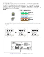
Page 4: ...g multiple V RVC PRO units Shielded cable is not mandatory however it may be necessary if EMI or RF interference is present at the installation site The V RVC PRO includes two RJ45 crimp on connectors Use a good quality RJ45 crimping tool to complete the connections Diagram B info factorelectronics com www factorelectronics com TIA EIA 568A Wiring Up to three V RVC PRO units can be daisy chained o...

Page 5: ...the RJ45 input of the V RVC PRO Then connect the RJ45 output of the V RVC PRO to the RJ45 input of the second V RVC PRO Now connect the RJ45 output of the last V RVC PRO to the V RVC input of the Factor Electronics amplifier Diagram D X Music Side View Power In RJ45 Out Connect The Cat5e To Any Factor Electronics Amplifier V RVC Input info factorelectronics com www factorelectronics com IN1 OUT1 I...

Page 6: ...able run from the V RVC PRO back to the amplifier and terminate at the V RVC RJ45 We recommend Cat5 6 cable runs of 100 max and shielded Cat5 6 runs of 200 300 max 2 Cat5 6 short cable run to the V RVC RJ45 then run a balanced 2 conductor 22 24awg shielded cable and terminate at the amplifier Using this method runs of 500 will be achievable Diagram E 1 Cat5 6 100 Shielded Cat5 6 200 Balanced Conne...

Page 7: ...onics com OUT IN RJ45 RJ45 1 Four selectable Dip switches RVC remote volume control 100Hz cut 15db pad 24V phantom power See detailed explanations on the next page 5 RJ45 Out1 Connect this to another V RVC PRO input in a daisy chain or to the V RVC input of the amplifier 2 VOX sensitivity adjustment 3 RJ45 IN Connect this to the OUT of another V RVC PRO in a daisy chain or from the output of an X ...

Page 8: ... volume controller by setting the switch to ON All other V RVC s must have this dipswitch set to OFF If more than one RVC is set to ON it will be impossible to control the master volume of the amplifier NOTE To effectively control the master volume of the amplifier from the V RVC set the amplifier master volume to 75 or 2 3rds full volume and control the overall level from the V RVC If the amplifi...

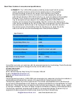
Page 9: ...tio Line 80dB Power Requirements 24V DC Dimensions Imperial W 2 75 x H 5 9 x D 1 96 Dimensions Metric W 115 5mm x H 114 5mm x D 45mm Shipping Weight 3lb 1 36kg Warranty 3 Years Specifications In an effort to provide our customers with the latest advancements in technology Factor Electronics Specifications are subject to change from time to time without notice Contact Information Factor Electronics...

Reviews: