Version 1.0
FX5632 Series User’s Quick Reference
Page 2/3
www.fabiatech.com
©2007 FabiaTech Corporation
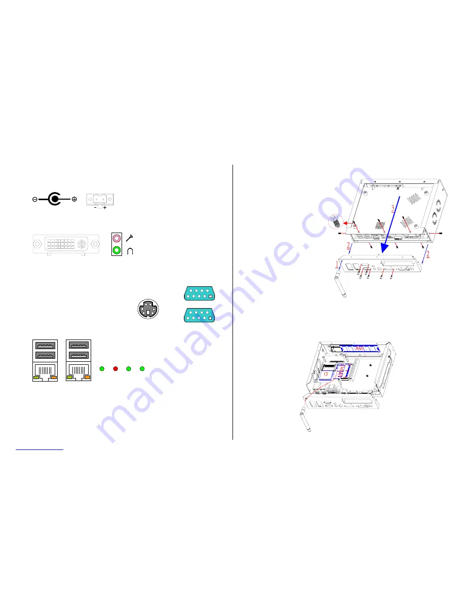
5. I/O outlets and LED Indicators
A. Power
Connector
B. DVI and Audio/Video Connectors
C. Keyboard/ Mouse and Serial Port Connectors
D. USB/LAN Connectors and LED Indicators (
RJ45
)
6. Software Configuration and Driver Installation
Please refer to the driver installing documentaion in the included Compact Disc for installing what
device driver you need. If you need to change the system settings or configurations of I/O ports, Please
refer to the User's Manual (also in the included Compact Disc) for details.
7. Installing the CompactFlash Module, Memory Module, and mini-PCI Module with
Antenna on FX5632x
Step 1: Release total 14 screws including 6 hexagonal screws on 2 D-sub and DVI connectors.
Step 2: Take off the wireless Antenna if it has been installed.
Step 3: Take off the rear panel and then the bottom cover.
Step 4: Install CompactFlash to the CF socket if necessary.
Step 5: Change the DDR module if necessary.
Step 6: Install mini-PCI module and wireless Antenna if necessary.
Step 7: Close bottom cover, rear panel, and fasten all screws with reversed sequence.
Keyboard & Mouse
1
1
COM2
5
9
6
COM1
5
Standard PS/2 keyboard can be plugged into this connector without any
adapter cable. If PS/2 keyboard and mouse will be used simultaneously,
the included Y-type adapter cable is needed.
6
9
The LAN port is a RJ45 connector with 2 LEDs. The right side
LED (orange) indicates data is accessing and the left side
LED (green) indicates on-line status. (When lighted indicates
on-line and off indicates off-line)
Note: LAN1 and LAN2 LEDs indicate
on-line/access status of LAN #1
and LAN #2 respectively.
PWR HDD LAN2 LAN1
DC +12 to +24V, 15% tolerance
FX5632: 58VA minimum.
FX5632A: 65VA minimum.
DC12~24V
Terminal Block
DC Plug-In Connector
Earphone
Mic-In
DVI (Including CRT Signals)
Before installing the above modules,
Please open the bottom cover and
rear panel as the right figure shown:


