


51
12
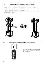
Del mismo modo, coloque la parte inferior de la chimenea y fije la parte inferior al marco utilizando
los 2 tornillos retirados previamente.
11
Solo para instalaciones sin conductos
Las instalaciones sin conductos
requieren un
Kit de conversión sin
conductos
cuyos componentes se
muestran en la
FIGURA 11
.
No utilice el REGISTRO para instalaciones
sin conductos. La TAPA DE LA CHIMENEA
INFERIOR debe ser desechada y
reemplazada por una nueva con
orificios del
Kit de conversión sin
conductos (D en la FIGURA 11)
.
Como se indica en la
FIGURA 11
,
coloque el DESVIADOR SIN CONDUCTO
(
A
) sobre la abertura de escape del EASY
CUBE (
E
). Ajuste las EXTENSIONES
HORIZONTALES DEL DESVIADOR SIN
CONDUCTO (
B
) en el DESVIADOR (
A
).
Version 02/12 - Page 8
FIGURE 13
MAKE THE ELECTRICAL CONNECTION
Remove the cover from the field wiring compartment.
(SEE
FIGURE 11)
DO NOT turn on the power until installation is
complete!
Connect the Power Supply Cable to the rangehood.
Connect the Green (Green and Yellow) ground wire under the
Green grounding screw. Attach the White lead of the power
supply to the White lead of the rangehood with a twist-on type
wire connector. Attach the Black lead of the power supply
to the Black lead of the rangehood with a twist-on type wire
connector.
1.
The UPPER CHIMNEY
COVER
(C in FIGURE 13)
attaches to the top of the
support structure using two
screws provided (
G in FIGURE
13
). If using the
High Ceiling
Chimney Kit
, use the UPPER
CHIMNEY COVER supplied
with the kit. Slide up and
attach the UPPER CHIMNEY
COVER.
2. Attach the duct work to the
DAMPER (
M in FIGURE 1
).
Make sure to seal all joints with
duct tape to prevent leaks.
3.
The LOWER CHIMNEY
COVER
(B in FIGURE 13)
attaches using two screws
provided (
G in FIGURE 13
).
Install the LOWER CHIMNEY
COVER by sliding it up over
the support and the UPPER
CHIMNEY COVER.
For ductless installations, line up the DUCTLESS DIVERTER
EXTENSIONS HORIZONTAL
(B in FIGURE 12)
with the holes
in the LOWER CHIMNEY COVER
(D in FIGURE 12)
and snap
in the VENT GRIDS
(C in FIGURE 12)
.
INSTALLING THE RANGEHOOD
A. Home power supply cable
B. Black wires
C. UL listed wire connectors
D.White wires
E. Green (or bare) ground wire from home power supply
connected to green ground screw
F. Range hood power supply cable
G.Range hood power supply cable connected to green
ground screw
FIGURE 11
Ductless installations require
a
Ductless Conversion
Kit
whose components are
pictured in
FIGURE 12
. Do
not use the DAMPER (
M
in FIGURE 1
) for ductless
installations.
The LOWER
CHIMNEY COVER
(B
in FIGURE 1)
should be
discarded and replaced by
the new one with holes from
the
Ductless Conversion Kit
(D in FIGURE 12)
.
As indicated in
FIGURE
12
, place the DUCTLESS
DIVERTER
(A)
over the
exhaust opening of the EASY
CUBE
(E)
. Fit the DUCTLESS
DIVERTER EXTENSIONS
HORIZONTAL
(B)
into the
DIVERTER
(A).
FIGURE 12
FOR DUCTLESS INSTALLATIONS
Summary of Contents for TRATTO TRATIS36SSV
Page 5: ...5 RANGEHOOD DIMENSIONS Min 24 Min 30 ...
Page 19: ...19 Wiring Diagram 991 0439 886 H90 305 D002531_01 ...
Page 24: ...24 DIMENSIONS DE LA HOTTE Min 24 Min 30 ...
Page 38: ...38 Wiring Diagram 991 0439 886 H90 305 D002531_01 ...
Page 43: ...43 DIMENSIONES DE LA CAMPANA Min 24 Min 30 ...
Page 57: ...57 991 0439 886 H90 305 D002531_01 Diagrama de cableado ...
Page 59: ...59 ...


