background image

Version 05/10- Page 5

TOOLS  NEEDED  FOR  INSTALLATION

• Saber Saw or Jig Saw

• Drill

• 1  1/4" Wood Drill Bit

• Pliers

• Phillips Screwdriver

• Flat Blade Screwdriver

• Wire Stripper or Utility Knife

• Metal Snips

• Measuring Tape or Ruler

• Level

• Pencil

• Caulking Gun

• Duct Tape

PARTS  SUPPLIED  FOR  INSTALLATION

• 1 Hardware Package

• 1 Literature Package

PARTS  NEEDED  FOR  INSTALLATION

• 2 Conduit Connectors

• Power Supply Cable

• 1 Wall or Roof Cap

• All Metal Ductwork

9 Feet Straight Duct

2 - 90˚ Elbows

Wall Cap

Total System

9.0 feet

10.0 feet

0.0 feet

19.0 feet

FIGURE  3

3.0 feet

5.0 feet

12.0 feet

0.0 feet

45˚ Elbow

90˚ Elbow

90˚ Flat Elbow

Wall Cap

FIGURE  2

CALCULATE  THE  DUCTRUN  LENGTH

The ductrun should not exceed 35 equivalent feet 

if ducted with the required minimum of 6" round 

ductwork.  Calculate the length of the ductwork 

by adding the equivalent feet in 

FIGURE 2

 for 

each piece of duct in the system  An example 

is given in 

FIGURE 3

.

For best results, use no more than three 90°  

elbows.  Make sure that there is a minimum of 

24" of straight duct between elbows if more 

than one is used.  Do not install two elbows 

together.  If you must elbow right away, do it 

as far away from the hood's exhaust opening 

as possible.

   WARNING

Because  of the weight  and size of the 

rangehood canopy, two or more people 

are needed to move and safely install the 

rangehood canopy.

Failure to properly lift rangehood could 

result in damage to the product or personal 

injury.

PERSONAL INJURY HAZARD

PLAN  THE  INSTALLATION

This rangehood  can be installed  as either ducted or ductless.  In a ducted 

application, this rangehood can be vented through the wall or ceiling.  To vent 

through a wall, a 90° elbow is used.  When installed ductless, the rangehood 

vents out of grates on the sides of the chimney.  Ductless installations require 

Ductless Conversion Kit

, available from your dealer.

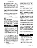
WARNING!

  BEFORE MAKING ANY CUTS OR HOLES FOR INSTALLATION, 

DETERMINE WHICH VENTING METHOD WILL BE USED AND CAREFULLY 

CALCULATE ALL MEASUREMENTS.

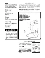
RANGEHOOD  COMPONENTS

!

FIGURE  1

A. CANOPY SECTION

B. LOWER CHIMNEY COVER

C. UPPER CHIMNEY COVER

D. CANOPY MOUNTING BRACKETS

E. CANOPY MOUNTING BRACKET 

F. MOUNTING SCREWS

G. CHIMNEY MOUNTING BRACKETS

H. DAMPER

I. CHIMNEY SCREWS

ADJUSTMENT SCREWS

A

B

C

D

E

F

G

H

I

CAUTION

To reduce risk of fire and to properly exhaust 

air, be sure to duct the air outside – Do not vent 

exhaust air into spaces within walls or ceilings 

or into attics, crawl spaces, or garages.

Summary of Contents for TENDER

Page 1: ...Part 280 Four wire power supply must be used and the appliance wiring must be revised See Electrical Requirements LISEZ BIEN CETTE FICHE AVANT D INSTALLER LA HOTTE AVERTISSEMENT POURMINIMISERLERISQUE...

Page 2: ...and at the junction box When making the electrical connection cut a 1 1 4 hole in the wall A hole cut through wood must be sanded until smooth A hole through metal must have a grommet WARNING TOREDUCE...

Page 3: ...ns du fabricant et entre en communication avec lui pour toute information Fermez le courant avant tout entretien et veillez a ce qu il reste ferm Si on ne peut pas verrouiller le panneaux du service l...

Page 4: ...Haut One 39 upper chimney to replace 21 10 16 upper chimney that came with hood Stainless 620000648 OPTIONAL ACCESSORIES AVAILABLE AND DIMENSIONS 24 high mounts to the wall beneath the rangehood for...

Page 5: ...must elbow right away do it asfarawayfromthehood sexhaustopening as possible WARNING Because of the weight and size of the rangehood canopy two or more people are needed to move and safely install the...

Page 6: ...sh will determine the bottom edge of the canopy 4 Thechimneymountsbytwobrackets 2inFIGURE5 Note the position of the brackets The top bracket should be installed about 1 8 away from the ceiling The bot...

Page 7: ...d Attach the White lead of the power supply to the White lead of the rangehood with a twist on type wire connector Attach the Black lead of the power supply to the Black lead of the rangehood with a t...

Page 8: ...ood system is designed to remove smoke cooking vapors and odors from the cooktop area For Best Results Start the rangehood several minutes before cooking to develop proper airflow Allow the unit to op...

Page 9: ...Halogen Lamps Cette hotte utilise les ampoule halog nes de 20 W WIRING DIAGRAM FOR 3 SPEED 280 CFM MODEL DIAGRAMME DE C BLAGE MOD LE 3 VITESSE 280 PCM CONTROL PANELS AND WIRING DIAGRAMS FIGURE 14 3 S...

Page 10: ...umbing 2 Service calls to repair or replace range hood light bulbs fuses or filters Those consumable parts are excluded from warranty coverage 3 Repairs when your range hood is used for other than nor...

Page 11: ...le mur un coude de 90 est utilis Lorsque install e sans conduit la ventilation s effectue par des grilles sur les c t s de la chemin e Les installations sans conduit requi rent un Kit Pour Conversion...

Page 12: ...Avant d installer les fixations installer les vis de r glage au bas de la fixation Ces deux vis sont fournies dans le n cessaire de ferrures et ont des t tes hexagonales avec une encoche pour un tourn...

Page 13: ...r 6 Brancher le c ble d alimentation sur la hotte Attacher le fil blanc du c ble d alimentation sur le fil blanc de la hotte avec une cosse Attacher le fil noir du c ble d alimentation au fil noir de...

Page 14: ...on et les odeurs de la cuisine Pour de meilleurs r sultats Mettre la hotte en circuit avant de commencer la cuisson Laisser l appareil fonctionner quelques minutes apr s la cuisson pour liminer la fum...

Page 15: ...les de votre maison ou pour corriger votre c blage ou votre syst me de plomberie 2 Les appels de service pour remplacer ou r parer les ampoules les fusibles ou les filtres de votre hotte de cuisini re...

Reviews: