


PREPARE THE WALL
1.
Disconnect and move freestanding range from cabinet
opening to provide easier access to upper cabinet and rear
wall. Put a thick, protective covering over cooktop, set-in
range or countertop to protect from damage or dirt.
2.
Determine and clearly mark with a pencil the center line
on the wall where the rangehood will be installed.
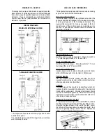
3.
The Nova attaches to the wall by three mounting brackets,
points 1, 2 and 3 in FIGURE 5. The canopy of the rangehood
hangs from two metal flanges that extend from bracket #1.
This bracket must be mounted with the flanges on the bottom
of the bracket. The dimensions in FIGURE 5 are for mounting
the canopy 24" above the cooking surface.
If a backsplash is to be used with this rangehood, it must be
installed before the rangehood. Installation instructions for
the backsplash are supplied in its box. The height of the
backsplash will determine the bottom edge of the canopy.
4.
The chimney attaches to the wall by two additional
brackets, points 2 and 3 in FIGURE 5 which illustrates the
positioning of the chimney brackets. The largest bracket,
#2, should be installed about 1/8" away from the ceiling.
The middle bracket ( bright metal ) must be installed with the
ends touching the wall and the curves facing outward. The
middle bracket must be installed at the bottom point of the
upper chimney sleeve.
Determine the proper location for each bracket and install the
brackets on the wall.
MAKE SURE THAT THE BRACKETS
ARE SECURELY FASTENED TO THE WALL.
5.
Determine and make all necessary cuts in the wall for
the ductwork. Install the ductwork before the rangehood.
6.
Determine the proper location for the Power Supply Cable
as indicated in FIGURE 6. Use a 1 1/4" Drill Bit to make this
hole. Run the Power Supply Cable. Use caulking to seal
around the hole. DO NOT turn on the power until installation
is complete. For remote blowers, a separate wiring cable is
required. DO NOT WIRE THE REMOTE BLOWER INTO
THE FIELD WIRING HOUSING OR CONNECT WITH THE
POWER SUPPLY CABLE.
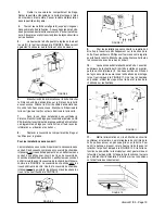
FIGURE 7
Version 11/00 - Page 5
INSTALL THE RANGEHOOD
1.
Remove the unit from the carton and place on a flat
surface for assembly. Cover the surface to prevent accidental
damage. Remove all parts including the mounting hardware
before discarding the carton.
2.
Remove the grease filters from the unit and set aside.
The grease filters are removed by pressing the handle in front
of the filter as indicated in FIGURE 7. When replacing, make
sure that the filters are properly positioned with the handles
in front and visible.
FIGURE 5
FIGURE 6
90 cm 35
3
/
8
" or 30"
Summary of Contents for Nova
Page 12: ...4324289...


