
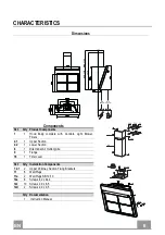


EN
7
7
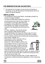
INSTALLATION
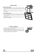
Wall drilling and bracket fixing
7.2.1
X
1
÷
2
11a
11
12a
1
1
2
+
A
A=Min 250
Max 400
7
1
0
+
A
1
2
1
2
200 200
180 180
A
On the wall, draw
• a Vertical line up to the ceiling or upper limit, at the centre of the area in which the Hood is
to be fitted;
• a Horizontal line at a minimum of (710 mm +
A
) above the Cooker Top.
• Mark a point
(1)
on the horizontal line, 200 mm to the right of the vertical reference line.
• Repeat this operation on the other side, checking that the two marks are level.
• Mark a reference point
(2)
as indicated at 180 mm from the vertical reference line and (112
mm +
A
) above the Cooker Top.
• Repeat this operation on the other side, checking that the two marks are level.
Drill at the points
(1)
marked, using a ø 12 mm drill bit.
• Drill at the points
(2)
marked, using a ø 8 mm drill bit.
• Insert the bracket plugs
11a
into the holes
1
and screw into place.
• Insert plug
11
into hole
2
.
• Place bracket
7.2.1
on the wall as shown about 1-2 mm from the ceiling or upper limit align-
ing the centre (notch) with the vertical reference line.
• Mark the wall at the centres of the holes in the bracket.
• Place bracket
7.2.1
on the wall as shown at X mm below the first bracket (X = height of the
upper chimney section supplied), aligning the centre (notch) with the vertical line.
• Mark the wall at the centres of the holes in the bracket.
• Drill ø 8 mm holes at all the centre points marked.
• Insert the wall plugs
11
in the holes.
• Fix the brackets using the
12a
screws (4,2 x 44,4) supplied.
Summary of Contents for MATRIX EG10 X A90 ACTIVE
Page 1: ...Instructions Manual Manual de instrucciones Kullanim Kilavuzu...
Page 15: ...GR 1 15 650 mm 120 mm 0 04 mbar 2...
Page 16: ...GR 1 16 3 mm 8...
Page 17: ...GR 1 17 2 4...
Page 21: ...GR 2 21 7 2 1 4 12c 2 9 x 9 5 2 12c 2 9 x 9 5 12c 2 1 2 2 2 7 2 1 12c 3 mm...
Page 23: ...GR 2 23 1 5 V LR03 AAA...
Page 24: ...GR 2 24 FG 2 24h Confort Panel Confort Panel...
Page 25: ...GR 2 25 FC 4 D 5 2 FC 1 FC 24h Confort Panel A B Confort Panel A B...
Page 27: ...RU 2 27 650 I 120 0 04 2...
Page 28: ...RU 2 28 3 8...
Page 29: ...RU 2 29 2 4...
Page 33: ...RU 3 33 7 2 1 4 12c 2 9 x 9 5 2 12c 2 9 x 9 5 12c 2 1 2 2 2 7 2 1 12c 3...
Page 35: ...RU 3 35 1 5 LR03 AAA...
Page 36: ...RU 3 36 FG 2 24 E...
Page 37: ...RU 3 37 FC 4 D 5 2 FC 1 FC 24 E A B A B...
Page 63: ...SA 6 63 650 I 120 0 04 2...
Page 64: ...SA 6 64 3 8...
Page 65: ...SA 6 65 2 4...
Page 68: ...SA 6 68 A Vr 11 a B 11 a Vr 11 A B Vr 9 150 9 120 12c 2 9 12 5 8 12d 2 9 9 5 16 12c 12d 8...
Page 69: ...SA 6 69 7 2 1 4 12 C 2 9 x 9 5 12c 2 1 2 2 2 7 2 1 12c...
Page 71: ...1 5 LR AAA 12 c 2 9 12 5 8 12 d 2 9 9 5...
Page 72: ...SA 7 72 FG 2 24 E...
Page 73: ...SA 7 73 FC 4 D 5 FC 1 FC 24 E A B A B...
Page 75: ......
Page 76: ...436005065_ver3 D002382_00...


