


Version 08/06 - Page 6
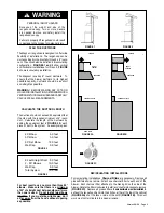
PREPARE THE CABINET
1.
Disconnect and move freestanding range from cabinet
opening to provide easier access to upper cabinet and rear
wall. Put a thick, protective covering over cooktops, set-in
ranges or countertops to protect from damage or dirt.
2.
Determine and clearly mark with a pencil the center
line of the cabinet on the wall and on the underside of the
cabinet where the rangehood will be installed.
3.
Determine the proper cutouts for the ductwork. Make
all necessary cuts in the walls or cabinets for the ductwork.
Install the ductwork before mounting the rangehood.
4.
If the cabinet bottom is recessed, wood filler strips need
to be installed.
5.
Drill four 3/16" clearance holes for hood mounting
screws.
FIGURE 4
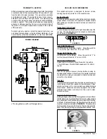
6
.
Cut a 6 1/2" diameter hole in cabinet bottom as
shown.
7.
Determine and make the proper cutout for the Power
Supply Cable. Use a 1 1/4" Drill Bit to make this hole. Run
the Power Supply Cable through the wall or cabinet. DO NOT
turn on the power until installation is complete. Use caulking
to seal around the wire opening.
FIGURE 5
FIGURE 6
8.
Remove the grease filters
USING TWO HANDS
by
pulling the knob out and turning to the left.
9.
Remove the terminal box cover (located on the back
wall of the hood. Remove the power supply cable knockout
using a flat-blade screwdriver. Attach strain relief in power
supply cable opening so that clamping screws are inside of
rangehood.
10.
Attach damper to exhaust opening on top of the range-
hood using the two small screws from the hardware pack-
age.
INSTALL THE RANGEHOOD
1.
Place the rangehood mounting screws close to the
holes in the cabinet bottom.
2.
Lift rangehood into place while feeding wiring through
strain relief.
3.
Insert the screws through the clearance holes and start
them into the rangehood.
4.
Connect the vent system to the rangehood and seal all
joints with duct tape.
5.
Connect the Power Supply Cable to the rangehood.
Attach the White lead of the power supply to the White lead
of the rangehood with a twist-on type wire connector. Attach
the Black lead of the power supply to the Black lead of the
rangehood with a twist-on type wire connector. Connect
the Green ( Green and Yellow ) ground wire under the Green
grounding screw.
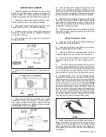
6.
Install the grease filters using two hands by first pulling
and turning the knob to the left so that the locking lever does
not protrude from the filter
(as in FIGURE 7)
. Insert the op-
posite end of the filter into the retaining channel. Insert the
knob end next, then turn knob to the right to lock the filter
into place.
FIGURE 7
7.
Turn the power supply on. Turn on blower and lights.
If the rangehood does not operate, check that the circuit
breaker is not tripped or the house fuse blown. If the unit still
does not operate, disconnect the power supply and check
that the wiring connections have been made properly.
Summary of Contents for Magnum
Page 12: ......


