Faber Diamante Isola Installation Instructions Manual Download Page 5

Version 08/06 - Page 5
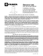
upper

chimney

cover

lower

chimney

cover

canopy

cabinet base

x = distance from hood to cooktop

(varies depending on installation)

min - 24”, suggested max - 30”

also consult cooktop

manufacturer's recommendation

  2 

3/4”

  min

15 

3/8”

 max

23 

5/8”

3/16”

36”

FIGURE 4

DUCTED 

DIMENSIONS

x

min & max ceiling height examples

x = 30"

min

7' 

11 9/16"

max

9'

 3/16"

x = 28"

min

7' 

9 9/16"

max

8' 

10 3/16"

x = 26"

min

7' 

7 9/16"

max

8' 

8 3/16"

x = 24"

min

7' 

5 9/16"

max

8' 

6 3/16"

The  Diamante  Isola  chimney  is  highly 

adjustable and designed to meet varying 

ceiling heights as indicated in 

FIGURE 4

The chimney can be adjusted for ceilings 

between 7'  5  9/16" and 9'  3/16" depending 

on  the  distance  between  the  bottom  of 

the hood and the cooktop 

(distance x in 

FIGURE 4)

.

For  higher  ceiling  installations,  the 

High 

Ceiling Chimney Kit

 includes an additional 

support structure which adds 27 1/2" to the  

ceiling heights in 

FIGURE 4


DUCTED 

INSTALLATION  DIMENSIONS


(vented to the outside)

PLAN  THE  INSTALLATION

This rangehood can be installed as either ducted or ductless.    When installed ductless, the rangehood vents out of a grate on 

the back of the lower chimney.  Ductless installations require a 

Ductless Conversion Kit

, available from your dealer.

WARNING!

  BEFORE MAKING ANY CUTS OR HOLES FOR INSTALLATION, DETERMINE WHICH VENTING METHOD WILL BE 

USED AND CAREFULLY CALCULATE ALL MEASUREMENTS.

   WARNING

DUE  TO  THE  SIZE 

AND  WEIGHT  OF  THIS 

R A N G E H O O D ,   T H E 

SUPPORT  MUST  BE 

FIRMLY  ATTACHED  TO 

THE CEILING.  For plaster 

or sheet rock ceilings, the 

support must be attached 

to  the  joists.    If  this  is 

not  possible,  a  support 

structure  must  be  built 

behind the plaster or sheet 

rock.    The  manufacturer 

assumes  no  responsibility 

for injury or damage caused 

by improper installations.

!

Summary of Contents for Diamante Isola

Page 1: ...a Nejamaislaisser un l ment de la table de cuisson fonctionner sans surveillance la puissance de chauffage maximale un renversement d bordement de mati re graisseuse pourrait provoquer une in ammation...

Page 2: ...ved if servicing is ever neces sary A UL Listed 1 2 conduit connector must be provided at each end of the power supply cable at the appliance and at the junction box When making the electrical connect...

Page 3: ...s conseils et mesuresdes curit dufournisseurtelsqueceuxpubli s par l Association Nationale de la Sauvegarde contre l Incendie et l Association Am ricaine d Ing nieurs de Chauffage Frigorifaction et Ai...

Page 4: ...on the outside bottom of the chimney cover Remove the UPPER CHIMNEY COVER C from the CHIMNEY SUPPORT D by removing the 2 philips screws on the outside top of the chimney cover CALCULATE THE DUCTRUN LE...

Page 5: ...tions the High CeilingChimneyKitincludesanadditional supportstructurewhichadds271 2 tothe ceiling heights in FIGURE 4 DUCTED INSTALLATION DIMENSIONS vented to the outside PLAN THE INSTALLATION This ra...

Page 6: ...esanadditional support structure which adds 27 1 2 to the various ceiling heights in FIGURE 5 upper chimney cover ductless lower chimney cover canopy cabinet base x distancefromhoodtocooktop varies de...

Page 7: ...ng two screws provided GinFIGURE10 If using the High Ceiling Chimney Kit use the UPPER CHIMNEY COVER supplied with the kit Slide up and attach the UPPER CHIMNEY COVER 2 Attach the duct work to the DAM...

Page 8: ...es not protrude from the lter as in FIGURE 14 Insert the opposite end of the lter into the retaining channel Insert the knob end next then turn knob to the right to lock the lter into place FIGURE 14...

Page 9: ...of each control button are indicated in FIGURE 15 Light On Off Button L On Off switch for the halogen lights Push the button in to turn the light ON push again to turn the light OFF Blower Indicator L...

Page 10: ...UIT Lalongueurduconduitnedoitjamaisexc der 35 pi s il s agit de conduit rond de 6 po Calculer la longueur du conduit en ajoutant l quivalent en pied de la FIGURE 2 pour chaque pi ce du conduit du syst...

Page 11: ...DES TROUS POUR L INSTALLATION D TERMINER QUELLE M THODE DE VENTILATION SERA UTILIS E ET CALCULER LES MESURES DE FA ON PR CISE La chemin e Diamante Isola est r glable pour diff rentes hauteurs de plafo...

Page 12: ...6 po max x 24 po min 7 pi 11 3 16 po max 8 pi 6 3 16 po DIMENSIONS D INSTALLATION SANS CONDUIT 121 2 po 3 3 16 po 3 1 2 1 CAUSE DE LA DIMENSION ET DU POIDS DE CETTE HOTTE LE SUPPORT DOIT TRE FIX FERME...

Page 13: ...erminer et marquer clairement l aide d un crayon la ligne centrale sur le mur o la hotte sera install e 3 Un gabarit L de la FIGURE 6 pourinstallerlesupportestfourni aveccedernier Utilisercegabarit po...

Page 14: ...otte Tirer sur le bouton et le tourner vers la gauche sens antihoraire de telle sorte que le levier de verrouillage ne fasse pas saillie hors du ltre Ins rer l extr mit comportant le bouton dans la ra...

Page 15: ...commandes est situ sur le devant de la hotte La position et la fonction de chaque bouton sont indiqu es la FIGURE 15 Bouton marche arr t de la lumi re L Interrupteur marche arr t pour la lumi re Pous...

Page 16: ...Version 08 06 Page 16...

Reviews: