


EN
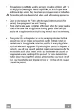
1
0
10
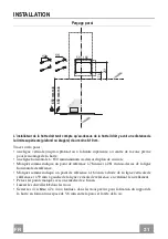
INSTALLATION
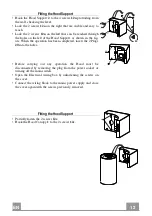
Drilling the Wall
12a
11
650 mm min
78
650 mm min
164
59
261
The person fitting the hood has to bear in mind that there must be a minimum distance of at least
8-10 Cm left between the top of the hood and the surface above it (ceiling or shelf).
Draw the following on the Wall:
• a Vertical line up to the ceiling or top surface, at the centre of the area in which the Hood is
to be fitted;
• a Horizontal line: 650 mm min. above the Hob;
• Mark a reference point, as indicated, 78 mm and 261 mm above the horizontal reference
line.
• Mark a reference point, as indicated, 164 mm to the right of the vertical reference line and
59 mm to the left of the vertical reference line, checking to ensure it is level.
• Drill the points marked using a ø 8 mm drill bit.
• Insert the plugs
11
into the holes.
• Tighten the 4 screws
12a
(4.2 x 44.4) provided in the hood support fixing bores, leaving a
gap of 5-6 mm between the wall and the heads of the screws.
Summary of Contents for Bios HFH X F32
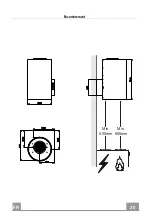
Page 9: ...EN 9 9 Dimensions Min 650mm Min 650mm...
Page 20: ...FR 2 0 20 Encombrement Min 650mm Min 650mm...
Page 31: ...DE 3 1 31 Platzbedarf Min 650mm Min 650mm...
Page 42: ...NL 4 2 42 Buitenafmetingen Min 650mm Min 650mm...
Page 53: ...ES 5 3 53 Dimensiones Min 650mm Min 650mm...
Page 60: ...GR 6 0 60 650 mm 120 mm...
Page 61: ...GR 6 1 61 0 04 mbar 8...
Page 62: ...GR 6 2 62...
Page 64: ...GR 6 4 64 Min 650mm Min 650mm...
Page 66: ...GR 6 6 66 8 2 12e 2 9 x 6 5 6 12d 3 4 4 12d 1 3 4 8 12d 1 3 4 12d 4 8 12e...
Page 67: ...GR 6 7 67 2 4 12a 2 12a 2 12a 2 20 12a 4X 20 2 12c 1 2 12c 12c...
Page 68: ...GR 6 8 68 2 12b 2 12c B A 12b A B...
Page 69: ...GR 6 9 69 T1 T2 T3 T4 L T1 T2 T3 T4 2 6 L...
Page 70: ...GR 7 0 70 2 4 5 A A B...
Page 71: ...RU 7 1 71 650 I 120...
Page 72: ...RU 7 2 72 0 04 8...
Page 73: ...RU 7 3 73...
Page 75: ...RU 7 5 75 Min 650mm Min 650mm...
Page 77: ...RU 7 7 77 8 2 12e 2 9 x 6 5 6 12d 3 4 4 12d 1 3 4 8 12d 1 3 4 12d 4 8 12e...
Page 78: ...RU 7 8 78 2 4 12a 2 12a 2 12a 2 20 12a 4X 20 2 12c 1 2 12c 12c...
Page 79: ...RU 7 9 79 2 12b 2 12c B A 12b A B...
Page 80: ...RU 8 0 80 T1 T2 T3 T4 L T1 T2 T3 T4 2 6 L...
Page 81: ...RU 8 1 81 2 4 5 A B A B...
Page 86: ...TR 8 6 86 Boyutlar Min 650mm Min 650mm...
Page 97: ...LT 9 7 97 Kli tis Min 650mm Min 650mm...
Page 108: ...LV 1 0 108 Izm ri Min 650mm Min 650mm...
Page 119: ...EE 1 1 119 M dud Min 650mm Min 650mm...
Page 130: ...FI 1 3 130 Mitat Min 650mm Min 650mm...


