Faber BELA30SS600-B Installation Instructions Manual Download Page 3

3

3.  When cutting or drilling into wall or ceiling, do not damage electrical wiring and 

other hidden utilities.

4.  Ducted fans must always be vented to the outdoors.

ALL  WALL  AND  FLOOR  OPENINGS  WHERE  THE  RANGEHOOD  IS  INSTALLED  MUST  

BE  SEALED.

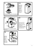
This rangehood requires at least 24" of clearance 

between the bottom of the rangehood 

and the cooking surface or countertop.  This hood has been approved by UL at this distance from 

the cooktop. Overhead cabinets on both sides of this unit must be a minimum of 18" above the 

cooking surface or countertop.  Consult the cooktop or range installation instructions given by 

the manufacturer before making any cutouts.  MOBILE  HOME  INSTALLATION  The installation 

of this rangehood must conform to the Manufactured Home Construction and Safety Standards, 

Title 24 CFR, Part 3280 (formerly Federal Standard for Mobile Home Construction and Safety, Title 

24, HUD, Part 280). See Electrical Requirements.

• Venting system MUST terminate outside the home.

• 

DO NOT

 terminate the ductwork in an attic or other enclosed space.

• 

DO NOT

 use 4" laundry-type wall caps.

• Flexible-type ductwork is not recommended.

• 

DO NOT

 obstruct the flow of combustion and ventilation air.

• Failure to follow venting requirements may result in a  fire.

   WARNING

!

Cold Weather installations

An additional back draft damper should be installed to minimize backward cold air flow and a 

nonmetallic thermal break should be installed to minimize conduction of outside temperatures as 

part of the vent system. The damper should be on the cold air side of the thermal break. The break 

should be as close as possible to where the vent system enters the heated portion of the house.

VENTING   REQUIREMENTS

Determine which venting method is best for your application.  Ductwork can extend either through the 

wall or the roof.

The length of the ductwork and the number of elbows should be kept to a minimum to provide efficient 

performance.  The size of the ductwork should be uniform.  Do not install two elbows together.  Use 

duct tape to seal all joints in the ductwork system.  Use caulking to seal exterior wall or floor opening 

around the cap.

Flexible ductwork is not recommended.  Flexible ductwork creates back pressure and air turbulence 

that greatly reduces performance.

Make sure there is proper clearance within the wall or floor for exhaust duct before making cutouts.  

Do not cut a joist or stud unless absolutely necessary.  If a joist or stud must be cut, then a supporting 

frame must be constructed. 

WARNING - To Reduce The Risk Of Fire, Use Only Metal Ductwork.

CAUTION - To reduce risk of fire and to properly exhaust air, be sure to duct air outside – Do 

not vent exhaust air into spaces within walls or ceilings or into attics, crawl spaces, or garages. 

Summary of Contents for BELA30SS600-B

Page 1: ...BELA30SS600 B BELA36SS600 B Installation Instructions Use and Care Information Instructions d installation Utilisez et d entretien BELLA 30 36...

Page 2: ...with your back to an exit Based on Kitchen Firesafety Tips published by NFPA WARNING TO REDUCE THE RISK OF FIRE OR ELECTRIC SHOCK do not use this fan with any solid state speed control device WARNING...

Page 3: ...ther installations An additional back draft damper should be installed to minimize backward cold air flow and a nonmetallic thermal break should be installed to minimize conduction of outside temperat...

Page 4: ...or grounding DO NOT ground to a gas pipe DO NOT have a fuse in the neutral or grounding circuit A fuse in the neutral or grounding circuit could result in electrical shock Check with a qualified elect...

Page 5: ...5 RANGEHOOD DIMENSIONS Min 24...

Page 6: ...4 12b 4 Screws 1 8 x 3 8 12c 2 Screws 12d 2 Screws 1 8 x 3 8 Qty Documentation 1 Instruction Manual Available Accessories Parts needed 6 Round Metal ductwork Direct Connect Wiring Box sku number WIREB...

Page 7: ...e Hood before connecting to the ductwork Only for Ducted Venting Installation Choose your ducting method Non Ducted Recirculation Option Ducted Venting Options Installation Requires purchase of Activa...

Page 8: ...e a bracket 7 2 1 on the wall as shown about 1 1 8 from the ceiling or upper limit aligning the center notch withtheverticalreferencelineandmarkthewallatthecentersoftheholesinthebracket Place the seco...

Page 9: ...he way to wall leaving 3 16 of the screw heads exposed Use a level to insure that Fixing Bracket is level and then fully secure the two screws Hook the hood body onto the hood body fixing bracket 7 3...

Page 10: ...nd the brackets 7 2 1 making sure that they are well seated Secure the sides to the brackets by using the 4 screws 12b 12a N 2x 12d 2 2 2 1 13 Slightly widen the two sides of the the lower chimney hoo...

Page 11: ...hind the brackets and connect to the Ductless Diverter mak ing sure that they are well seated 14 15 12a Only for the recirculation version connect the hood to the Air outlet Fix the lower Bracket 7 2...

Page 12: ...Consult a qualified electrician if the grounding instructions are not completely understood or if doubt exists as to whether the appliance is properly grounded Do not use an extension cord If the pow...

Page 13: ...widen the two sides of the the lower chimney hood and hook them between the upper section and the wall making sure that they are properly housed Fix the the lower chim ney hood laterally to the hood b...

Page 14: ...ry second while the motor is running It is disabled by pressing the button When the filters alarm is triggered the alarm can be reset by pressing and holding this button for approximately 3 seconds Th...

Page 15: ...elyno effectontheefficiencyofthefilteritself Replace takingcaretoensurethatthehandlefacesforwards Replacing Activated Charcoal Filter Itcannotbewashedorregenerated andmustbechangedwhen theFCsymbolonth...

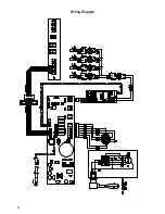
Page 16: ...16 Wiring Diagram...

Page 17: ...om accident alteration misuse abuse fire flood acts of God improper installation installation not in accordance with electrical or plumbing codes or Faber documentation or use of products not approved...

Page 18: ...nevoiedesortiesetrouvederri revouspendantquevous teignezlesflammes D apr sleguide KitchenFiresafetyTips publi parlaNFPAaux tats Unis AVERTISSEMENT POURR DUIRELERISQUED INCENDIEOUDECHOC LECTRIQUE n uti...

Page 19: ...tion doit pr voir un registre antirefoulement suppl mentaire pour r duire le flux d air froid inverse ainsi qu une barri re thermique non m tallique pour r duire la conduction destemp raturesext rieur...

Page 20: ...ILISEZ PAS une conduite de gaz pour la mise la terre N INSTALLEZ PAS un fusible sur le circuit neutre ou le circuit de mise la terre La pr sence d un fusible dans le circuit neutre ou de mise la terre...

Page 21: ...21 Min 24 DIMENSIONS DE LA HOTTE...

Page 22: ...x3 8 12c 2 Vis 12d 2 Vis1 8 x3 8 Qt Documentation 1 Moded emploi Accessoires disponibles Pi ces requises Conduitm tallique6 circulaire Bo tier de connexion directe No d article WIREBOX Trousse de che...

Page 23: ...der aux conduits Pour installation avec ventilation canalis e uniquement Choisissez la m thode de canalisation Sans canalisation Option de recirculation Options d installation avec ventilation canalis...

Page 24: ...1 sur le mur comme illustr environ 1 1 8 du plafond ou de la limite sup rieure en alignant le centre encoche avec la ligne de r f rence verticale Marquez l emplacement du centre des trous du support...

Page 25: ...ion comme illustr Ne les vissez pas compl tement au mur mais laissez libre 3 16 de la t te des vis Utilisezunniveaupourvousassurerquelabridedefixation est niveau puisvissez fondlesdeuxvis Engagez le b...

Page 26: ...hemin e sup rieureet engagez lesder ri relesbrides 7 2 1 envous assurantqu ils sontsolidement ancr s Fixezlesc t sauxbrides l aidedes4vis12b cartezl g rementlesdeux c t sdelasectioninf rieure delachem...

Page 27: ...e 7 2 1 inf rieure l aide de deux vis 12a fournies comme illustr Fixez le d flecteur de recyclage l aide de deux vis 12a fournies comme illustr cartez l g rement les deux c t s de la chemin e sup rieu...

Page 28: ...prenez pas parfaitement les instructions de mise la terre ou si vous avez des doutes quant la mise la terre de l appareil N utilisez pas de rallonge Si le cordon d alimentation est trop court demandez...

Page 29: ...tion inf rieure de la chemin e de hotte et assemblez les entre la section sup rieure et le mur en vous assur ant qu ils sont correcte ment install s Fixez la section inf rieure de la chemin e de hotte...

Page 30: ...0 minutes par heure Affiche 24 et le point en bas droite clignote une fois par seconde alors que le moteur est en fonction Appuyer sur la touche pour d brancher L alarme filtres tant activ e appuyer s...

Page 31: ...decedernier Lesremonterenveillant cequelapoign esoittoujoursvers lapartievisibleexterne Replacing Activated Charcoal Filter Nonlavableetnonr g n rable ildoit treremplac l affichage deFCouaumoinstousle...

Page 32: ...32 Sch ma de c blage...

Page 33: ...es d coulant d un accident d une modification de l utilisation incorrecte ou abusive d un incendie d une inondation d un cas de force majeure d une installation inad quate d une installation non confo...

Page 34: ...34...

Page 35: ...35...

Page 36: ...991 0454 810_02 160504 D002767_01...

Reviews: