


EN
1
0
10
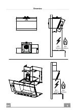
INSTALLATION
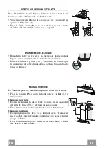
Wall drilling and bracket fixing
11a
1
1
2
2
140
11
12a
164
164
788
540
450
140
X
1÷2
7.2.1
As a first step, proceed with the following drawings:
• a vertical line up to the ceiling or up to the upper limit, at the centre of the area in which the
hood is to be fitted;
• a horizontal line at a minimum 788 mm above the cooker top.
• Mark a point
(1)
on the horizontal line, 164 mm to the right of the vertical reference line.
• Repeat this operation on the other side, checking that the two marks are levelled.
• Mark a reference point
(2)
as indicated at 140 mm from the vertical reference line and 540
mm above the cooker top.
• Repeat this operation on the other side, checking that the two marks are levelled.
• Drill at the marked points
(1)
, using a ø 12 mm drill bit.
• Drill at the marked points
(2)
using a ø 8 mm drill bit.
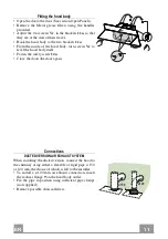
• Insert the bracket plugs
11a
into the holes (
1)
and tighten the screws.
• Insert plug
11
into holes
(2)
.
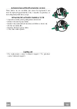
To install a decorative chimney ( optional )
• Place bracket
7.2.1
on the wall, about 1-2 mm from the ceiling or from the upper limit,
aligning the centre (notch) with the vertical reference line.
• Mark the wall at the centres of the bracket holes.
• Place the bracket
7.2.1
on the wall at X mm below the first bracket (X = height of the upper
chimney section), aligning the centre (notch) with the vertical line.
• Mark the wall at the centres of the bracket holes.
• Drill ø 8 mm holes at all the marked centre points.
• Insert the wall plugs
11
in the holes.
• Fix the brackets using the
12a
screws (4,2 x 44,4) supplied with the hood.
Summary of Contents for 110.0205.822
Page 4: ...4 4 137 140 142 145 146 SA...
Page 9: ...EN 9 9 Dimensions...
Page 20: ...FR 2 0 20 Encombrement...
Page 31: ...DE 3 1 31 Platzbedarf...
Page 42: ...ES 4 2 42 Dimensiones...
Page 49: ...GR 4 9 49 650 mm 120 mm...
Page 50: ...GR 5 0 50 0 04 mbar 8...
Page 51: ...GR 5 1 51...
Page 53: ...GR 5 3 53...
Page 55: ...GR 5 5 55 Vr 11a 11a Vr 12a 12a Vr 11a o150 120 mm o120 mm 9 150 9 120...
Page 57: ...GR 5 7 57 T1 T2 T3 T4 L T1 T2 T1 T2 T3 T1 T3 2 30 T1 T2 T3 T4 T4 T1 T4 2 6 L...
Page 58: ...GR 5 8 58 2 Comfort Panel comfort panel...
Page 59: ...GR 5 9 59 4 Comfort Panel A B comfort panel A B...
Page 60: ...RU 6 0 60 650 I 120...
Page 61: ...RU 6 1 61 0 04 8...
Page 62: ...RU 6 2 62...
Page 64: ...RU 6 4 64...
Page 66: ...RU 6 6 66 Vr 11a 2 11a Vr 12a 12a Vr 11a 150 120 120 9 150 9 120...
Page 68: ...RU 6 8 68 T1 T2 T3 T4 L T1 T2 T1 T2 T3 T1 T3 2 30 T1 T2 T3 T4 T4 T1 T4 2 6 L...
Page 69: ...RU 6 9 69 2 Comfort Comfort...
Page 70: ...RU 7 0 70 4 B A B...
Page 75: ...FI 7 5 75 Mitat...
Page 86: ...PL 8 6 86 Wymiary...
Page 97: ...TR 9 7 97 Boyutlar...
Page 108: ...NO 1 0 108 Dimensjoner...
Page 119: ...HU 1 1 119 Helysz ks glet...
Page 130: ...LT 1 3 130 Kli tis...
Page 137: ...SA 1 3 137 650 I 120...
Page 138: ...SA 1 3 138 0 04 8...
Page 139: ...SA 1 3 139...
Page 141: ...SA 1 4 141...
Page 143: ...SA 1 4 143 Vr 11a 11a Vr 12a 12a Vr 11a 120 150 120 9 150 9 120...
Page 145: ...T1 T2 T3 T4 L T1 T1 T2 T2 T1 T3 T3 T1 T2 T3 T4 2 30 T1 T4 T4 2 6 L SA 145...
Page 146: ...SA 1 4 146...
Page 147: ...SA 1 4 147 4 A B A B...


