background image

Page | 4 


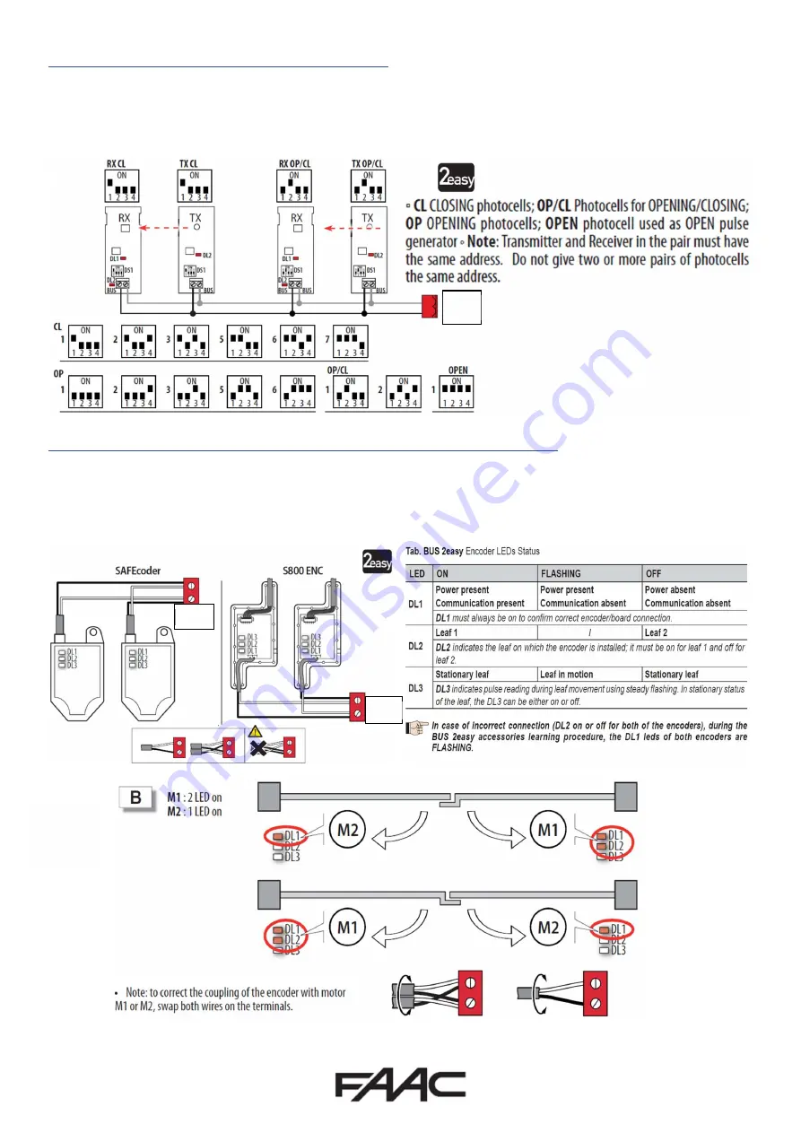
Connection of FAAC BUS 2Easy Photocells 


Connection of FAAC BUS 2easy Safecoders and S800 Encoders 


The E124 Control Board also allows for the use of FAAC BUS 2easy photocells which allow for simpler cabling, a reduced power 
consumption, and Failsafe checking of each device independently. The Failsafe checking being performed by our proprietary 
FAAC BUS 2easy communication protocol also assist the installer by removing the need for separate cabling for a monitoring 
circuit. (Please note that FAAC BUS photocells are only compatible with FAAC Control Boards and those using the BUS Terminal 
or using the BUS Relay Interface Board). 

J3 

The E124 Control Board also allows for the use of FAAC BUS 2easy Safecoders and the S800/S450 Encoders (required for 
operation  these  operators).  This  allows  for  the  control  board  to  have  positional  accuracy  and  allows  for  the  possibility  of 
inherent obstacle detection (Force Testing with the use a calibrated instrument to BS EN 12445/12453 norms (such as the 
Microtronics Blueforce Tester, available from FAAC UK) will be required to confirm suitability but please note that additional 
devices maybe required such as Safety Edges). 

J3 

J3 

Summary of Contents for E124

Page 1: ...E124 Quick Start Guide...

Page 2: ...operating correctly immediately or after installation BUS 2EASY ENCODER and PHOTOCELLS Cable Specification 2 core 0 5mm2 Multi Strand Shielded Cable with the Sheath connected to the Earth at one end P...

Page 3: ...are in the closed position as detailed on Page 8 d Run Time Learning tL function and follow procedure as detailed on Page 8 12 Provide an opening command to verify that the system works correctly 13...

Page 4: ...UTS DL5 IN5 STATUS LED DEFAULT FSW CL NORMAL STATE ON J5 CONNECTOR FOR OUTPUT 2 OUT2 DL6 FCA1 STATUS LED LIMIT SWITCH OPEN IF GATE CLOSED ON J6 CONNECTOR FOR TRAVEL LIMITS DL7 FCC2 STATUS LED LIMIT SW...

Page 5: ...se note that FAAC BUS photocells are only compatible with FAAC Control Boards and those using the BUS Terminal or using the BUS Relay Interface Board J3 The E124 Control Board also allows for the use...

Page 6: ...The first parameter that MUST be set is the CF This will then allow correct configuration to proceed Please note that until SETUP as been completed the display will show a flashing 50 which is SETUP r...

Page 7: ...ult power and speed settings will be sufficient to allow the first setup These values will generally require further adjustments if force limitation is being used as part of the safety systems and a n...

Page 8: ...Page 7 The below in the figure is what should be seen as an example for a double gate that is using encoders...

Page 9: ...e 8 The above is the Status references is what will be seen under normal operation even if the alarm LED is illuminated To identify the error the signalling Errors and Alarms procedure should be follo...

Page 10: ...he typical wiring of a Maglock using either OUT 1 or OUT 2 with a relay and separate power supply which are configurable as per below in Advance Programming The following parameters from Advanced Prog...

Page 11: ...Page 10 Signalling Errors and Alarms...

Page 12: ...rial Videos available for programming remote controls FAAC UK have created tutorial videos to assist the installer in the programming of remote controls Please use the link below to navigate straight...

Reviews: