

Chapter 4
Switch Hardware and Functionality
4 - 22
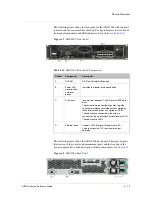
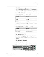
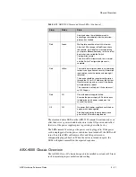
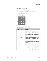
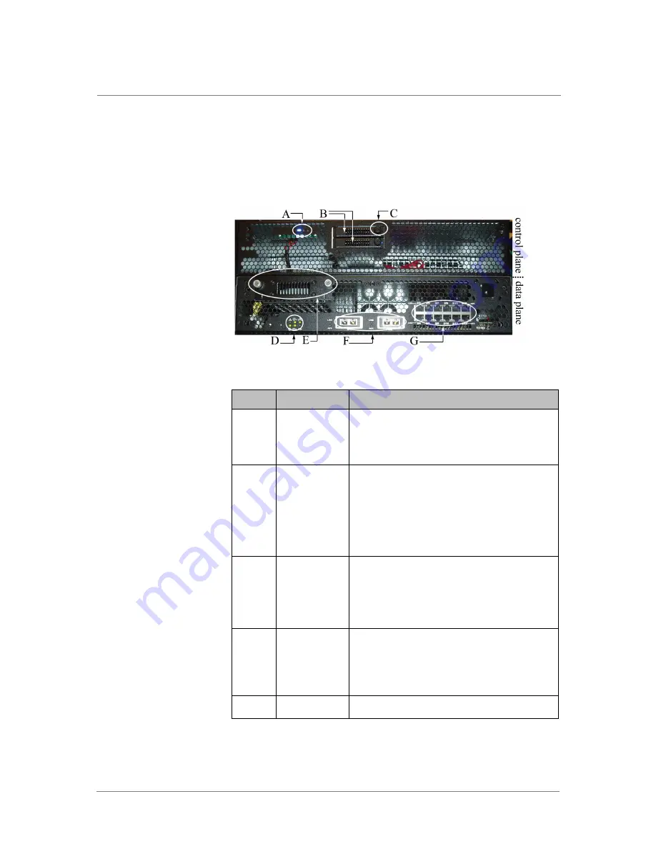
The following figure shows the front panel of the ARX-4000 with the bezel
removed. The figure displays the location of front panel components (the
drive bays and Ethernet ports, for example) and indicators such as status
LEDs. For a description of these components and indicators, see
Table 4.22
.
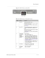
Figure 4.12
ARX-4000 Front Panel– Bezel Removed
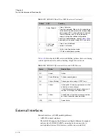
Table 4.22
ARX-4000 Front Panel Components and Descriptions
Callout
Component
Description
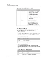
A
Control plane
LED and power
and reset
buttons
Front control plane LED, indicating the application
of power. For specifics, see
ARX-4000 Control
Plane LED and Button Functions, on page 4-24
.
B
Drive bays
The ARX-4000 includes two redundant 146 GB
internal SAS hard disks, that store the software
image, configuration files, log files, and other
maintenance-related data, configured as RAID1.
These drives are connected to the primary
controller on the ACM.
These drives are FRUs.
C
Drive LEDs
Each drive has an LED to the right of the drive. The
possible LED states are as follows:
• Flickering blue indicates disk activity.
• Continuous amber indicates a critical or
non-recoverable error condition.
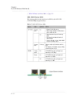
D
Data plane
LEDs
Front panel data plane LEDs indicate PCI link
status, NVRAM battery status, data plane power
supply status, and various operational states. For
specifics, see
ARX-4000 Data Plane LED
Functions, on page 4-25
.
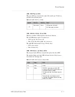
E
NVRAM
NV (Non-Volatile) RAM battery.
Summary of Contents for ARX-500
Page 1: ...ARX Hardware Reference Guide MAN 0338 00...
Page 2: ......
Page 6: ...vi...
Page 7: ...Table of Contents...
Page 8: ......
Page 12: ......
Page 26: ...Chapter 1 Introduction 1 16...
Page 27: ...2 ARX Overview ARX Functional Overview ARX Platform Models Managing the Switch...
Page 28: ......
Page 36: ...Chapter 2 ARX Overview 2 10...
Page 37: ...3 System Specifications System Specifications System Power Requirements Cable Requirements...
Page 38: ......
Page 56: ......
Page 87: ...Index...
Page 88: ......


